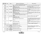

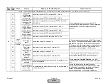
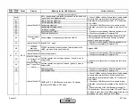
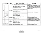


Error
Code
Diag.
Code
Device
Display
Meaning for the LMV5x System
Corrective Action
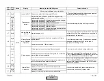
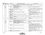
18
CAN warning level
1) If fault occurs sporadically: Reduce electrical noise.
2) If fault occurs constantly: Replace AZL5I
1A
EEPROM fault
1) If the error occurs in phase 22 together with a VSD,
check the wiring of the VSD
2) If fault occurs sporadically: Reduce electrical noise.
3) If fault occurs constantly: Replace AZL5I
1B
No valid
Parameter
Backup
Fault during copying of a parameter page
Back up LMV5 parameters to AZL. A prompt for this
comes up when exiting the Params & Display menu.
1C
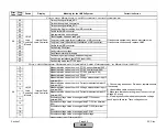
Page in EEPROM was disrupted, has been restored
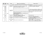
20
Display fault
22
RTC is locked, permanently busy
24
Buffer for page copies too small
28
Time stamp could not be sent
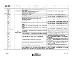
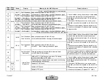
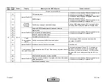
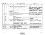
30
Fault
Communication
eBUS
Fault in connection with eBUS communication
Check wiring on RJ45 connector, located on the
underside of the AZL5..
38
Internal Fault AZL Interface mode could not be terminated
Reset the unit.
40
Communication
AZL with PC tool
Parameterization fault PC tool. Disclosed by key value check in
AZL
Check cable between AZL and PC. A null modem
adapter must be used on the 9 pin connector if the
cable does not have this internally. A USB-to-serial
adapter is OK to use when connecting the AZL to a
laptop.
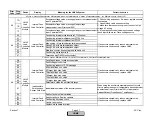
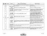
88
RAM fault with redundant inverse variables
89
Program run fault, execution of program code that will probably
never be executed
8A
Unintentional watchdog reset
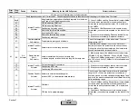
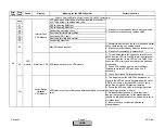
Internal Fault AZL
Internal Fault AZL
1) If fault occurs sporadically: Reduce electrical noise.
2) If fault occurs constantly: Replace AZL5I
1) If fault occurs sporadically: Reduce electrical noise.
2) If fault occurs constantly: Replace AZL5I
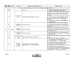
Fault with AZL5…
A7
AZL5
Internal Fault AZL
Section 7
Page 50
SCC Inc.
HOME
HOME
Summary of Contents for LMV 5 Series
Page 2: ...Intentionally Left Blank ...
Page 41: ...LMV Series Technical Instructions Document No LV5 1000 SCC Inc Page 7 Section 2 HOME ...
Page 42: ...Technical Instructions LMV Series Document No LV5 1000 Section 2 Page 8 SCC Inc HOME ...
Page 43: ...LMV Series Technical Instructions Document No LV5 1000 SCC Inc Page 9 Section 2 HOME ...
Page 44: ...Technical Instructions LMV Series Document No LV5 1000 Section 2 Page 10 SCC Inc HOME ...
Page 45: ...LMV Series Technical Instructions Document No LV5 1000 SCC Inc Page 11 Section 2 HOME ...
Page 46: ...Technical Instructions LMV Series Document No LV5 1000 Section 2 Page 12 SCC Inc HOME ...
Page 47: ...LMV Series Technical Instructions Document No LV5 1000 SCC Inc Page 13 Section 2 HOME ...
Page 48: ...Technical Instructions LMV Series Document No LV5 1000 Section 2 Page 14 SCC Inc HOME ...
Page 49: ...LMV Series Technical Instructions Document No LV5 1000 SCC Inc Page 15 Section 2 HOME ...
Page 50: ...Technical Instructions LMV Series Document No LV5 1000 Section 2 Page 16 SCC Inc HOME ...
Page 51: ...LMV Series Technical Instructions Document No LV5 1000 SCC Inc Page 17 Section 2 HOME ...
Page 52: ...Technical Instructions LMV Series Document No LV5 1000 Section 2 Page 18 SCC Inc HOME ...
Page 53: ...LMV Series Technical Instructions Document No LV5 1000 SCC Inc Page 19 Section 2 HOME ...
Page 54: ...Technical Instructions LMV Series Document No LV5 1000 Section 2 Page 20 SCC Inc HOME ...
Page 55: ...LMV Series Technical Instructions Document No LV5 1000 SCC Inc Page 21 Section 2 HOME ...
Page 373: ...Intentionally Left Blank ...