
LMV Series
Technical Instructions
Document No. LV5-1000
SCC Inc.
Page 1
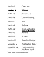
Section 2
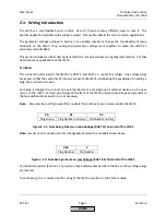
2-1: Wiring Introduction
The LMV5 is a very flexible burner control. As such, there are many different ways to wire it. The
specific application will dictate the wiring required. This section details the most common applications.
The parameter settings outlined in Section 3 can enable, disable or change the functionality of many
terminals on the LMV5. Thus, wiring and parameter settings work together to make the LMV5 an
extremely versatile BMS.
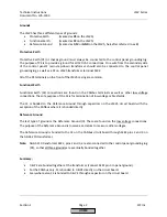
This section includes terminal descriptions (Section 2-2) and extensive wiring diagrams (Section 2-3) that
detail the many applications of the LMV5.
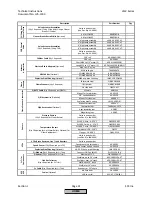
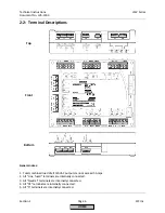
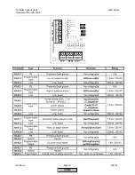
Terminals
The connection terminals of the LMV5 are RAST 5 and RAST 2.5 connectors (plugs). Line voltage plugs
are keyed so that they will only fit into one socket of the LMV5, eliminating the possibility of inserting a
plug into an incorrect socket.
Each plug is designed to connect one external device or a small group of external devices, such as gas
valves, to the LMV5. Each group of plugs on the front of the LMV5 provides line voltage and grounds so
that an additional terminal strip is not necessary.
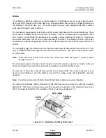
Note:
All protective earth grounds (PE), neutrals (N) and lines (L) are common inside the LMV5.
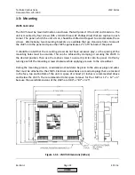
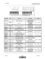
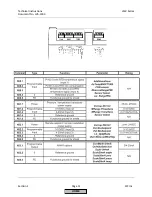
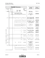
X9-
01.
04
Plug Group
Plug Number in Group
Pin Number on Plug
Figure 2-1.1: Numbering Scheme on
Line Voltage
(RAST 5) Terminals of the LMV5
Note:
Dashes or dots can be used interchangeably between the numbers shown above.
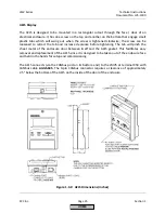
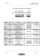
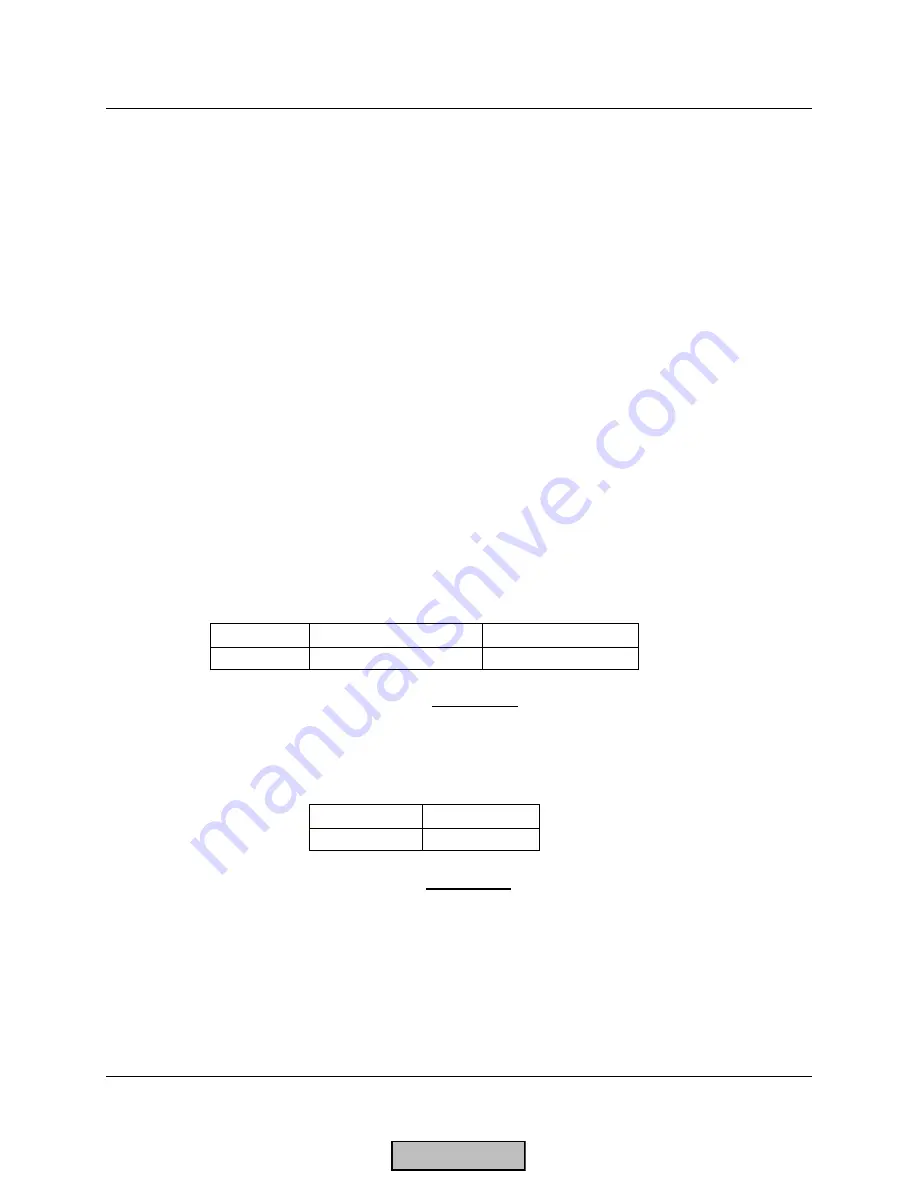
X62.
2
Plug Number
Pin Number
Figure 2-1.2: Numbering Scheme on
Low Voltage
(RAST 2.5) Terminals of the LMV5
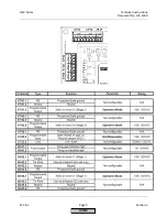
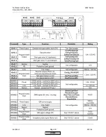
Terminal descriptions (Section 2-2) provide a map outlining exactly where the line and low voltage plugs
are located.
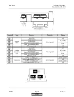
For each plug, Pin 1 is marked on the casing of the LMV5 as well as on the PLL52 module.
HOME
Summary of Contents for LMV 5 Series
Page 2: ...Intentionally Left Blank ...
Page 41: ...LMV Series Technical Instructions Document No LV5 1000 SCC Inc Page 7 Section 2 HOME ...
Page 42: ...Technical Instructions LMV Series Document No LV5 1000 Section 2 Page 8 SCC Inc HOME ...
Page 43: ...LMV Series Technical Instructions Document No LV5 1000 SCC Inc Page 9 Section 2 HOME ...
Page 44: ...Technical Instructions LMV Series Document No LV5 1000 Section 2 Page 10 SCC Inc HOME ...
Page 45: ...LMV Series Technical Instructions Document No LV5 1000 SCC Inc Page 11 Section 2 HOME ...
Page 46: ...Technical Instructions LMV Series Document No LV5 1000 Section 2 Page 12 SCC Inc HOME ...
Page 47: ...LMV Series Technical Instructions Document No LV5 1000 SCC Inc Page 13 Section 2 HOME ...
Page 48: ...Technical Instructions LMV Series Document No LV5 1000 Section 2 Page 14 SCC Inc HOME ...
Page 49: ...LMV Series Technical Instructions Document No LV5 1000 SCC Inc Page 15 Section 2 HOME ...
Page 50: ...Technical Instructions LMV Series Document No LV5 1000 Section 2 Page 16 SCC Inc HOME ...
Page 51: ...LMV Series Technical Instructions Document No LV5 1000 SCC Inc Page 17 Section 2 HOME ...
Page 52: ...Technical Instructions LMV Series Document No LV5 1000 Section 2 Page 18 SCC Inc HOME ...
Page 53: ...LMV Series Technical Instructions Document No LV5 1000 SCC Inc Page 19 Section 2 HOME ...
Page 54: ...Technical Instructions LMV Series Document No LV5 1000 Section 2 Page 20 SCC Inc HOME ...
Page 55: ...LMV Series Technical Instructions Document No LV5 1000 SCC Inc Page 21 Section 2 HOME ...
Page 373: ...Intentionally Left Blank ...