


Technical
Instructions
LMV
Series
Document
No.
LV5
‐
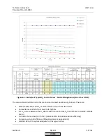
1000
Section
6
Page
8
SCC
Inc.
NOTE:
Both
sensors
are
required
to
do
a
boiler
efficiency
calculation.
The
boiler
efficiency
calculation
is
not
required
for
O
2
trim
operation.
If
sensors
are
activated
but
not
reading
correctly
or
not
wired
correctly,
the
O
2
trim
will
not
activate.
Burner
inlet
temperature
must
be
read
to
perform
a
temperature
‐
compensated
startup
on
the
LMV52.440.
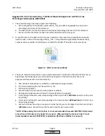
4.
Set
the
appropriate
actuators
to
“air
influen”
(air
influenced).
These
are
typically
only
the
actuators
/
VSD
that
will
directly
influence
the
burner
air
rate.
The
menu
path
for
these
parameters
is:
Params
&
Display
>
RatioControl
>
Gas
Settings
Typically,
only
the
air
actuator
and
the
VSD
(if
used)
are
set
to
air
influenced.
If
used,
the
FGR
actuator
is
usually
not
set
to
air
influenced.
5.
Set
the
operating
mode
of
the
O
2
system
to
“man
deact”
(manually
deactivated).
This
is
necessary
for
the
O
2
system
curves
to
be
commissioned.
The
menu
path
for
this
parameter
is:
Params
&
Display
>
O2Contr/Alarm
>
Gas
Settings
>
OptgMode
=
man
deact
6.
Set
the
curve
point
at
which
the
low
fire
delay
time
will
be
measured.
This
is
typically
set
to
Point
2,
unless
oversized
exhaust
stacks
with
high
turndown
burners
are
encountered,
which
may
make
gas
velocity
in
the
stack
too
low
at
low
fire.
For
these
applications,
setting
this
parameter
to
a
higher
point
than
Point
2
will
increase
the
gas
velocity
past
the
O
2
sensor
and
yield
a
more
responsive
O
2
reading.
This
can
be
set
through
the
following
menu
path:
Params
&
Display
>
O2Contr/Alarm>
Gas
Settings
>
Control
Param
>
LowfireAdaptPtNo
7.
Set
the
load
value
at
which
the
O
2
trim
will
disengage.
Typically,
this
is
set
to
the
load
value
for
Point
2
on
the
Fuel
‐
Air
Ratio
Control
Curve.
The
exception
to
this
is
if
parameter
LowfireAdaptPtNo
is
set
to
a
point
other
than
Point
2.
If
this
is
the
case,
set
this
for
the
load
value
that
corresponds
to
the
point
set
by
LowfireAdaptPtNo
.
This
can
be
set
through
the
following
menu
path:
Params
&
Display
>
O2Contr/Alarm
>
Gas
Settings
>
Control
Param
>
O2
CtrlThreshold
8.
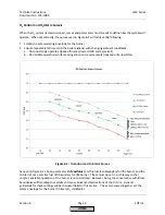
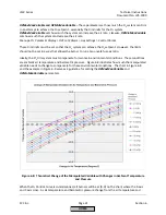
Set
the
desired
type
of
pre
‐
control.
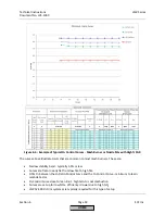
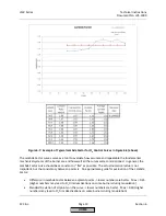
For
most
natural
gas
burners
where
the
gap
between
O
2
curves
is
large
enough
that
the
Lambda
Factor
can
be
learned
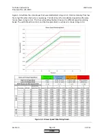
(see
O
2
Control
and
O
2
Alarm
Curves
in
Figure
6
‐
2),
this
should
be
set
to
"like
P
air".
The
"like
theory"
setting
is
typically
used
for
oil
burners,
and
"LambdaFact1"
should
only
be
used
as
a
last
resort.
The
menu
path
for
setting
the
type
of
pre
‐
control
is:
Params
&
Display
>
O2Contr/Alarm
>
Gas
Settings
>
Control
Param
>
Type
Air
Change
HOME
Summary of Contents for LMV 5 Series
Page 2: ...Intentionally Left Blank ...
Page 41: ...LMV Series Technical Instructions Document No LV5 1000 SCC Inc Page 7 Section 2 HOME ...
Page 42: ...Technical Instructions LMV Series Document No LV5 1000 Section 2 Page 8 SCC Inc HOME ...
Page 43: ...LMV Series Technical Instructions Document No LV5 1000 SCC Inc Page 9 Section 2 HOME ...
Page 44: ...Technical Instructions LMV Series Document No LV5 1000 Section 2 Page 10 SCC Inc HOME ...
Page 45: ...LMV Series Technical Instructions Document No LV5 1000 SCC Inc Page 11 Section 2 HOME ...
Page 46: ...Technical Instructions LMV Series Document No LV5 1000 Section 2 Page 12 SCC Inc HOME ...
Page 47: ...LMV Series Technical Instructions Document No LV5 1000 SCC Inc Page 13 Section 2 HOME ...
Page 48: ...Technical Instructions LMV Series Document No LV5 1000 Section 2 Page 14 SCC Inc HOME ...
Page 49: ...LMV Series Technical Instructions Document No LV5 1000 SCC Inc Page 15 Section 2 HOME ...
Page 50: ...Technical Instructions LMV Series Document No LV5 1000 Section 2 Page 16 SCC Inc HOME ...
Page 51: ...LMV Series Technical Instructions Document No LV5 1000 SCC Inc Page 17 Section 2 HOME ...
Page 52: ...Technical Instructions LMV Series Document No LV5 1000 Section 2 Page 18 SCC Inc HOME ...
Page 53: ...LMV Series Technical Instructions Document No LV5 1000 SCC Inc Page 19 Section 2 HOME ...
Page 54: ...Technical Instructions LMV Series Document No LV5 1000 Section 2 Page 20 SCC Inc HOME ...
Page 55: ...LMV Series Technical Instructions Document No LV5 1000 SCC Inc Page 21 Section 2 HOME ...
Page 373: ...Intentionally Left Blank ...