
LMV
Series
Technical
Instructions
Document
No.
LV5
‐
1000
SCC
Inc.
Page
15
Section
4
4.
On
B2,
write
down
the
burner
ID
if
it
is
not
blank.
If
the
burner
ID
on
B2
is
not
the
same
as
B1,
change
the
burner
ID
on
B2
to
match
B1.
Changing
the
burner
ID
can
be
done
using
the
following
menu
path:
Updating
>
BurnerID
The
OEM
level
password
will
be
required
to
change
the
burner
ID.
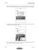
5.
Power
off
B2
LMV5.
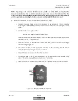
After
B2
LMV5
is
powered
off,
remove
the
AZL
from
B2
and
replace
with
the
AZL
from
B1.
Power
B2
LMV5
back
on.
6.
Now
that
the
burner
IDs
match
or
the
B2
burner
ID
is
blank,
the
B1
parameter
set
can
be
downloaded
into
B2
using
the
following
menu
path:
Updating
>
ParamBackup
>
AZL
‐
>
LMV5x
The
OEM
or
service
level
password
for
B2
will
be
necessary
to
access
this.
This
will
download
all
of
the
parameters
from
B1
AZL
into
the
LMV5
on
B2.
This
process
may
take
up
to
5
minutes.
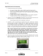
This
process
is
complete
when
the
AZL
states
"Backup
Restore
finished
Parameter
BC
:
Complete"
or
“Backup
Restore
finished
Parameter
BC
:
Partial".
Do
not
interrupt
this
process
once
it
is
started.
Also,
the
alarm
output
will
be
energized
when
the
new
parameter
set
is
downloaded
to
B2
LMV5.
7.
After
this
is
complete,
B2
can
be
powered
down.
The
AZL
from
B1
can
be
returned
to
B1
and
the
AZL
from
B2
can
be
reconnected
to
B2.
Power
B2
LMV5
back
on.
8.
If
the
burner
ID
on
B2
was
changed
to
allow
the
backup,
then
return
the
burner
ID
to
what
it
was
previously.
If
the
burner
ID
was
blank
before
the
download,
change
the
burner
ID
on
B2
to
a
unique
value
different
than
B1.
Typically,
the
burner
serial
number
is
used.
NOTE:
An
exact
copy
of
all
parameters
is
transferred
when
the
above
procedure
is
executed,
including
light
‐
off
positions,
Fuel
Air
Ratio
Control
Curves
and
O
2
Curves.
Typically,
even
"identical"
burners
and
boilers
need
unique
light
‐
off
positions,
Fuel
Air
Ratio
Control
Curves
and
O
2
curves.
Since
this
is
typically
the
case,
curves
and
ignition
positions
are
typically
deleted
after
the
parameter
set
is
downloaded
into
a
new
burner.
Suggested
Initial
Light
‐
off
for
LMV5
Systems
1.
The
following
procedure
assumes
the
following:
a.
Fuel
train
"Pilot
GP2"
was
selected
for
a
gas
pilot
burner.
b.
Pre
‐
requisites
for
Basic
LMV51
systems
or
LMV52
systems
(from
above)
are
met.
c.
Procedure
for
Configuring
(Parameterization
of)
an
LMV5
has
been
done
(from
above).
d.
This
is
a
first
‐
time
commissioning
of
the
LMV5
and
the
combustion
control
curve
is
blank
(no
points
are
entered).
2.
Close
manual
main
fuel
(gas)
valve
that
is
downstream
of
the
pilot
take
‐
off.
HOME
Summary of Contents for LMV 5 Series
Page 2: ...Intentionally Left Blank ...
Page 41: ...LMV Series Technical Instructions Document No LV5 1000 SCC Inc Page 7 Section 2 HOME ...
Page 42: ...Technical Instructions LMV Series Document No LV5 1000 Section 2 Page 8 SCC Inc HOME ...
Page 43: ...LMV Series Technical Instructions Document No LV5 1000 SCC Inc Page 9 Section 2 HOME ...
Page 44: ...Technical Instructions LMV Series Document No LV5 1000 Section 2 Page 10 SCC Inc HOME ...
Page 45: ...LMV Series Technical Instructions Document No LV5 1000 SCC Inc Page 11 Section 2 HOME ...
Page 46: ...Technical Instructions LMV Series Document No LV5 1000 Section 2 Page 12 SCC Inc HOME ...
Page 47: ...LMV Series Technical Instructions Document No LV5 1000 SCC Inc Page 13 Section 2 HOME ...
Page 48: ...Technical Instructions LMV Series Document No LV5 1000 Section 2 Page 14 SCC Inc HOME ...
Page 49: ...LMV Series Technical Instructions Document No LV5 1000 SCC Inc Page 15 Section 2 HOME ...
Page 50: ...Technical Instructions LMV Series Document No LV5 1000 Section 2 Page 16 SCC Inc HOME ...
Page 51: ...LMV Series Technical Instructions Document No LV5 1000 SCC Inc Page 17 Section 2 HOME ...
Page 52: ...Technical Instructions LMV Series Document No LV5 1000 Section 2 Page 18 SCC Inc HOME ...
Page 53: ...LMV Series Technical Instructions Document No LV5 1000 SCC Inc Page 19 Section 2 HOME ...
Page 54: ...Technical Instructions LMV Series Document No LV5 1000 Section 2 Page 20 SCC Inc HOME ...
Page 55: ...LMV Series Technical Instructions Document No LV5 1000 SCC Inc Page 21 Section 2 HOME ...
Page 373: ...Intentionally Left Blank ...