

LMV
Series
Technical
Instructions
Document
No.
LV5
‐
1000
SCC
Inc.
Page
21
Section
6
O2MaxManVariable
and
O2MinManVariable
–
These
parameters
set
how
much
the
O
2
system
can
trim
in
an
attempt
to
achieve
the
O
2
setpoint
‐
essentially
the
trim
limits
for
the
O
2
system.
O2MaxManVariable
sets
how
much
the
system
can
increase
the
air
rate.
Likewise,
O2MinManVariable
sets
how
much
the
system
can
decrease
the
air
rate.
Menu
path:
Params
&
Display
>
O2Contr/Alarm
>
Gas
Settings
>
Control
Param
These
trim
limits
must
be
set
so
that
the
O
2
system
can
achieve
the
O
2
setpoint.
However,
the
limits
should
not
be
set
in
a
way
that
allows
the
burner
to
run
at
an
unsafe
fuel
‐
air
ratio.
Ideally,
the
O
2
trim
system
must
compensate
for
two
main
environmental
conditions.
These
conditions
are
ambient
air
temperature
and
barometric
pressure.
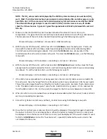
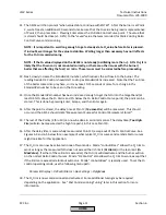
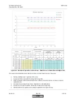
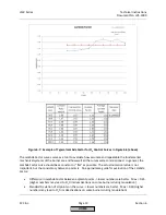
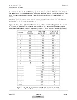
Figure
6
‐
8
illustrates
how
much
the
manipulated
variable
needs
to
change
to
compensate
for
these
environmental
conditions.
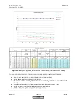
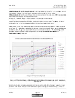
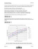
The
chart
in
Figure
6
‐
8
and
the
example
in
Figure
6
‐
9
serve
as
a
guideline
for
setting
the
O2MaxManVariable
and
O2MinManVariable
parameters.
Figure
6
‐
8:
Theoretical
Change
of
the
Manipulated
Variable
with
Changes
in
Ambient
Temperature
and
Pressure
When
the
O
2
Control
Curve
is
commissioned,
all
burners
will
be
at
(0,
0)
on
the
chart,
where
the
X
‐
axis
and
Y
‐
axis
cross.
As
air
temperature
and
barometric
pressure
change
from
the
air
temperature
and
HOME
Summary of Contents for LMV 5 Series
Page 2: ...Intentionally Left Blank ...
Page 41: ...LMV Series Technical Instructions Document No LV5 1000 SCC Inc Page 7 Section 2 HOME ...
Page 42: ...Technical Instructions LMV Series Document No LV5 1000 Section 2 Page 8 SCC Inc HOME ...
Page 43: ...LMV Series Technical Instructions Document No LV5 1000 SCC Inc Page 9 Section 2 HOME ...
Page 44: ...Technical Instructions LMV Series Document No LV5 1000 Section 2 Page 10 SCC Inc HOME ...
Page 45: ...LMV Series Technical Instructions Document No LV5 1000 SCC Inc Page 11 Section 2 HOME ...
Page 46: ...Technical Instructions LMV Series Document No LV5 1000 Section 2 Page 12 SCC Inc HOME ...
Page 47: ...LMV Series Technical Instructions Document No LV5 1000 SCC Inc Page 13 Section 2 HOME ...
Page 48: ...Technical Instructions LMV Series Document No LV5 1000 Section 2 Page 14 SCC Inc HOME ...
Page 49: ...LMV Series Technical Instructions Document No LV5 1000 SCC Inc Page 15 Section 2 HOME ...
Page 50: ...Technical Instructions LMV Series Document No LV5 1000 Section 2 Page 16 SCC Inc HOME ...
Page 51: ...LMV Series Technical Instructions Document No LV5 1000 SCC Inc Page 17 Section 2 HOME ...
Page 52: ...Technical Instructions LMV Series Document No LV5 1000 Section 2 Page 18 SCC Inc HOME ...
Page 53: ...LMV Series Technical Instructions Document No LV5 1000 SCC Inc Page 19 Section 2 HOME ...
Page 54: ...Technical Instructions LMV Series Document No LV5 1000 Section 2 Page 20 SCC Inc HOME ...
Page 55: ...LMV Series Technical Instructions Document No LV5 1000 SCC Inc Page 21 Section 2 HOME ...
Page 373: ...Intentionally Left Blank ...