

LMV
Series
Technical
Instructions
Document
No.
LV5
‐
1000
SCC
Inc.
Page
11
Section
4
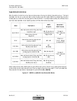
NOTE:
Depending
on
the
direction
of
rotation,
home
position
set
in
the
LMV5,
and
whether
the
actuator
is
activated
or
deactivated,
the
actuator
may
rotate
as
soon
as
it
is
addressed.
For
this
reason
it
is
highly
recommended
that
the
actuator
shaft
be
uncoupled
from
the
valve
/
damper
until
the
parameters
pertaining
to
the
above
are
set,
and
the
initial
LMV5
alarm
is
reset.
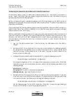
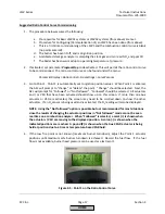
5.
Address
the
actuators.
This
is
accomplished
by
the
following
steps:
a.
Remove
the
outer
black
cover
of
all
actuators
to
be
addressed.
This
is
done
by
loosening
the
three
Philips
(Pozidriv)
head
screws
on
the
cover
and
setting
the
cover
aside.
b.
On
the
AZL,
the
menu
path
will
be:
Params
&
Display
>
Actuators
>
Addressing
Note
that
when
the
“Params
&
Display”
menu
is
entered,
it
may
be
necessary
to
enter
the
OEM
or
service
level
password.
c.
Select
the
actuator
to
be
addressed.
When
prompted,
press
the
“Enter”
key
to
begin
the
addressing
assignment.
d.
Press
the
red
button
on
the
appropriate
actuator.
If
done
correctly,
the
AZL
should
state
that
the
address
assignment
was
successful.
e.
Repeat
the
procedure
above
for
the
other
actuators.
f.
The
jumper
must
be
set
to
"Bus
termination"
on
the
last
device
on
the
CANbus
daisy
chain.
The
last
device
could
be
an
actuator
or
a
PLL
module.
g.
After
all
actuators
are
successfully
addressed,
the
outer
black
covers
can
be
reinstalled.
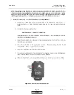
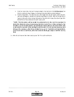
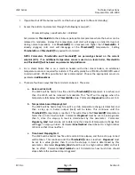
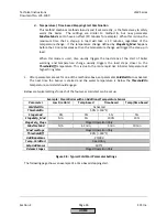
Figure
4
‐
3:
Actuator
with
Cover
Removed
HOME
Summary of Contents for LMV 5 Series
Page 2: ...Intentionally Left Blank ...
Page 41: ...LMV Series Technical Instructions Document No LV5 1000 SCC Inc Page 7 Section 2 HOME ...
Page 42: ...Technical Instructions LMV Series Document No LV5 1000 Section 2 Page 8 SCC Inc HOME ...
Page 43: ...LMV Series Technical Instructions Document No LV5 1000 SCC Inc Page 9 Section 2 HOME ...
Page 44: ...Technical Instructions LMV Series Document No LV5 1000 Section 2 Page 10 SCC Inc HOME ...
Page 45: ...LMV Series Technical Instructions Document No LV5 1000 SCC Inc Page 11 Section 2 HOME ...
Page 46: ...Technical Instructions LMV Series Document No LV5 1000 Section 2 Page 12 SCC Inc HOME ...
Page 47: ...LMV Series Technical Instructions Document No LV5 1000 SCC Inc Page 13 Section 2 HOME ...
Page 48: ...Technical Instructions LMV Series Document No LV5 1000 Section 2 Page 14 SCC Inc HOME ...
Page 49: ...LMV Series Technical Instructions Document No LV5 1000 SCC Inc Page 15 Section 2 HOME ...
Page 50: ...Technical Instructions LMV Series Document No LV5 1000 Section 2 Page 16 SCC Inc HOME ...
Page 51: ...LMV Series Technical Instructions Document No LV5 1000 SCC Inc Page 17 Section 2 HOME ...
Page 52: ...Technical Instructions LMV Series Document No LV5 1000 Section 2 Page 18 SCC Inc HOME ...
Page 53: ...LMV Series Technical Instructions Document No LV5 1000 SCC Inc Page 19 Section 2 HOME ...
Page 54: ...Technical Instructions LMV Series Document No LV5 1000 Section 2 Page 20 SCC Inc HOME ...
Page 55: ...LMV Series Technical Instructions Document No LV5 1000 SCC Inc Page 21 Section 2 HOME ...
Page 373: ...Intentionally Left Blank ...