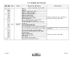
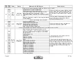
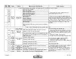
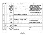
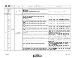
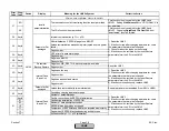
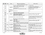
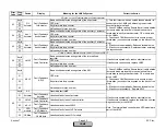
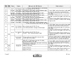

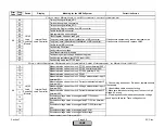
Error
Code
Diag.
Code
Device
Display
Meaning for the LMV5x System
Corrective Action
Any #
00
01I
03
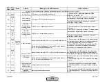
Basic unit has detected extraneous light during startup
01 = QRI / QRB, 02 = ION / UV, 03 = any (LMV52 only)
Any #
00
01I
03
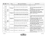
Basic unit has detected extraneous light during shutdown
01 = QRI / QRB, 02 = ION / UV, 03 = any (LMV52 only)
Any #
00
01I
03
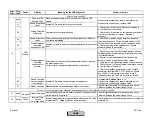
No flame detected at the end of safety time TSA1 or TSA2
01 = QRI / QRB, 02 = ION / UV, 03 = any (LMV52 only)
Any #
00
01I
03
(LMV52 only) Loss of flame during normal operation
01 = QRI / QRB, 02 = ION / UV, 03 = any (LMV52 only)
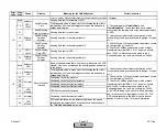
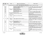
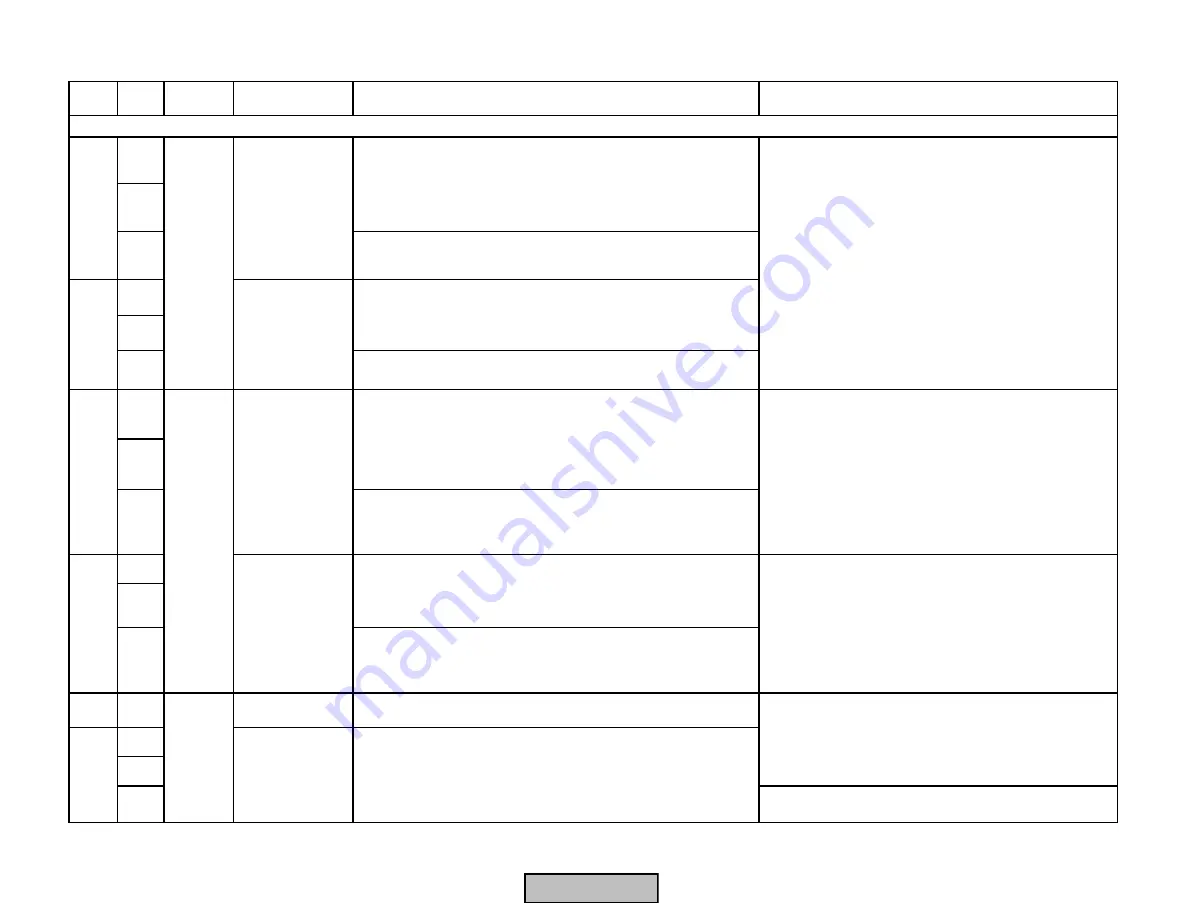
27
Any #
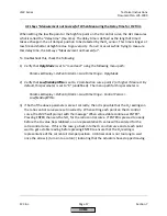
Air Pressure on Air pressure = on, but should have been off
Any #
00
01
The error message may be traced back to an open
safety loop / burner flange.
1) Make sure blower starts in phase 22 and shuts off in
phase 78 or 83 (see sequence diagrams).
2) Check the setpoint on the air pressure switch. Raise
setpoint if necessary. Switch should open after
postpurge.
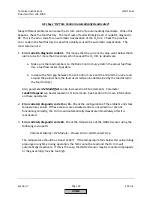
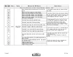
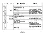
No flame detected at the end of safety time TSA1 or TSA2.
Loss of flame during normal operation (phase 60-62)
Air pressure = off, but should have been on
1) Check flame detector for signal in the presence of
flame using a flame source. Replace if detector does
not generate the anticipated signal.
2) Check for flame signal "decay" as burner refractory
heats up. If this happens, a UV scanner may be
needed.
3) Increase setting of
ReacTmeLossFlame
.
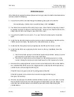
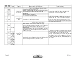
Basic unit has detected extraneous light during shutdown
1) Ensure that the source of extraneous light is not a
flame. If it is a flame, take corrective action
immediately.
2) If the QRI scanner is used, ambient light can cause
an extraneous light error. Ensure sensor is viewing a
dark area such as the inside of a boiler.
3) If the QRI scanner is used, check for glowing
refractory. If glowing refractor is the cause, the
afterburn time may need to be lengthened or a UV
scanner may have to be used.
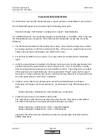
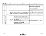
Basic unit has detected extraneous light during startup
1) With a piloted gas train, this means that the pliot did
not light. Check wiring of ignition transformer and pilot
valve.
2) Check manual shutoff valves for the pilot gas.
3) Check position of air damper. Close further if
necessary. Pilot may be blowing out.
4) Check flame detector for signal in the presence of
flame using a flame source. Replace if detector does
not generate the anticipated signal.
LMV5 /
Flame
Detect.
Loss of Flame
Extraneous Light
on Shutdown
No Flame at End
of Safety Time
Fault with devices or wiring connected to the Base Unit (LMV5)
28
Air Pressure off
Devices
conn. to
LMV5
Extraneous Light
on Startup
25
26
23
24
LMV5 /
Flame
Detect.
Section 7
Page 31
SCC Inc.
HOME
HOME
Summary of Contents for LMV 5 Series
Page 2: ...Intentionally Left Blank ...
Page 41: ...LMV Series Technical Instructions Document No LV5 1000 SCC Inc Page 7 Section 2 HOME ...
Page 42: ...Technical Instructions LMV Series Document No LV5 1000 Section 2 Page 8 SCC Inc HOME ...
Page 43: ...LMV Series Technical Instructions Document No LV5 1000 SCC Inc Page 9 Section 2 HOME ...
Page 44: ...Technical Instructions LMV Series Document No LV5 1000 Section 2 Page 10 SCC Inc HOME ...
Page 45: ...LMV Series Technical Instructions Document No LV5 1000 SCC Inc Page 11 Section 2 HOME ...
Page 46: ...Technical Instructions LMV Series Document No LV5 1000 Section 2 Page 12 SCC Inc HOME ...
Page 47: ...LMV Series Technical Instructions Document No LV5 1000 SCC Inc Page 13 Section 2 HOME ...
Page 48: ...Technical Instructions LMV Series Document No LV5 1000 Section 2 Page 14 SCC Inc HOME ...
Page 49: ...LMV Series Technical Instructions Document No LV5 1000 SCC Inc Page 15 Section 2 HOME ...
Page 50: ...Technical Instructions LMV Series Document No LV5 1000 Section 2 Page 16 SCC Inc HOME ...
Page 51: ...LMV Series Technical Instructions Document No LV5 1000 SCC Inc Page 17 Section 2 HOME ...
Page 52: ...Technical Instructions LMV Series Document No LV5 1000 Section 2 Page 18 SCC Inc HOME ...
Page 53: ...LMV Series Technical Instructions Document No LV5 1000 SCC Inc Page 19 Section 2 HOME ...
Page 54: ...Technical Instructions LMV Series Document No LV5 1000 Section 2 Page 20 SCC Inc HOME ...
Page 55: ...LMV Series Technical Instructions Document No LV5 1000 SCC Inc Page 21 Section 2 HOME ...
Page 373: ...Intentionally Left Blank ...