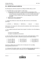

Technical Instructions
LMV Series
Document No. LV5-1000
Section 8
Page 14
SCC Inc.
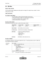
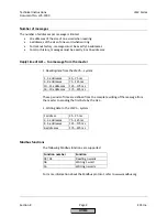
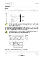
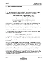
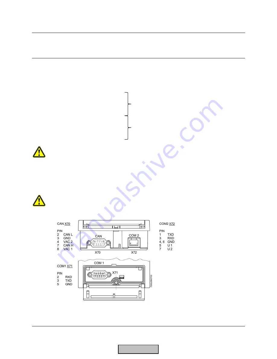
AZL5 interface
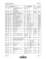
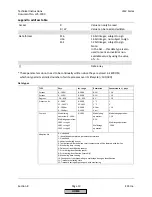
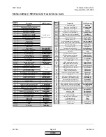
General
The AZL... serves the Modbus via its COM2 port (8-pole Western jack RJ45). The port is assigned to the
functional low-voltage range.
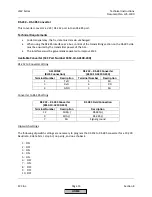
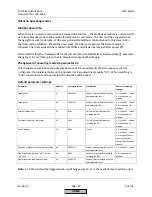
Assignment of RJ45 pins:
PIN
1
TXD (RS-232 level or V28)
2
Not used
3
RXD (RS-232 level or V28)
4
GND
5
U1 (typ8.2V)
6
GND
7
U2 (typically -8.2V)
8
Not used
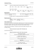
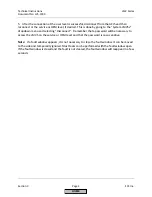
When preparing and fitting a connecting cable between the AZL... and a converter, it is to be
noted that PIN 5 and PIN 7 can deliver a current of 5 mA each. Adequate insulation against
other potentials must be ensured.
The maximum permissible data line length between COM2 and a converter is 3 m. In exceptional cases,
this data line length can be exceeded, depending on environmental conditions (electrical interference)
and the type of cable used – without Siemens assuming responsibility.
To ensure protection against electric shock hazard, it must be made certain that AC 120 V
lines are strictly separated from the functional low-voltage area.
Note: COM1 (PC port) and COM2 cannot be active at the same time!
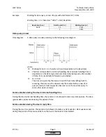
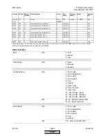
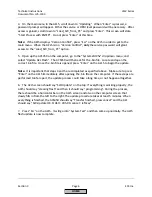
Modbus
eBUS
HOME
Summary of Contents for LMV 5 Series
Page 2: ...Intentionally Left Blank ...
Page 41: ...LMV Series Technical Instructions Document No LV5 1000 SCC Inc Page 7 Section 2 HOME ...
Page 42: ...Technical Instructions LMV Series Document No LV5 1000 Section 2 Page 8 SCC Inc HOME ...
Page 43: ...LMV Series Technical Instructions Document No LV5 1000 SCC Inc Page 9 Section 2 HOME ...
Page 44: ...Technical Instructions LMV Series Document No LV5 1000 Section 2 Page 10 SCC Inc HOME ...
Page 45: ...LMV Series Technical Instructions Document No LV5 1000 SCC Inc Page 11 Section 2 HOME ...
Page 46: ...Technical Instructions LMV Series Document No LV5 1000 Section 2 Page 12 SCC Inc HOME ...
Page 47: ...LMV Series Technical Instructions Document No LV5 1000 SCC Inc Page 13 Section 2 HOME ...
Page 48: ...Technical Instructions LMV Series Document No LV5 1000 Section 2 Page 14 SCC Inc HOME ...
Page 49: ...LMV Series Technical Instructions Document No LV5 1000 SCC Inc Page 15 Section 2 HOME ...
Page 50: ...Technical Instructions LMV Series Document No LV5 1000 Section 2 Page 16 SCC Inc HOME ...
Page 51: ...LMV Series Technical Instructions Document No LV5 1000 SCC Inc Page 17 Section 2 HOME ...
Page 52: ...Technical Instructions LMV Series Document No LV5 1000 Section 2 Page 18 SCC Inc HOME ...
Page 53: ...LMV Series Technical Instructions Document No LV5 1000 SCC Inc Page 19 Section 2 HOME ...
Page 54: ...Technical Instructions LMV Series Document No LV5 1000 Section 2 Page 20 SCC Inc HOME ...
Page 55: ...LMV Series Technical Instructions Document No LV5 1000 SCC Inc Page 21 Section 2 HOME ...
Page 373: ...Intentionally Left Blank ...