

Technical Instructions
LMV Series
Document No. LV5-8000
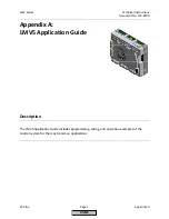
Appendix A
Page 14
SCC Inc.
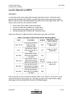
Low Fire Hold with an RWF55
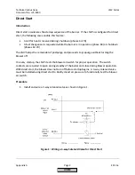
Introduction
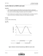
Low fire hold assists in preventing boiler damage from thermal shock. If an RWF55 is the
external load controller with the LMV5, a low fire hold can be easily incorporated. With an
RWF55, a low fire hold is accomplished by breaking the increase load signal to the LMV5. The
wiring and setup for four cases will be described:
•
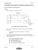
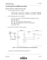
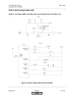
Steam boiler with an RWF55 with analog output
•
Hot water boiler with an RWF55 with analog output
•
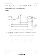
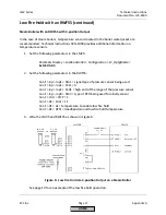
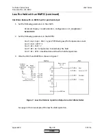
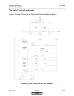
Steam boiler with an RWF55 with 3-position output
•
Hot water boiler with an RWF55 with 3-position output
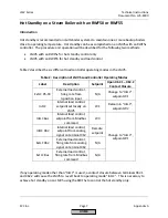
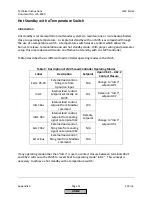
Table 4 describes the six different load controller operating modes in the LMV5.
Table 4: Description of LMV5 Load Controller Operating Modes
Label
Description
Setpoint
Upon X62.1 – X62.2
Contact Closure
ExtLC X5-03
External load control,
firing rate from
3-position input
N/A
Change to “IntLC”,
setpoint W1
IntLC
Internal load control,
setpoint set locally on
LMV5
W1
Remain in “IntLC”,
setpoint W2
IntLC Bus
Internal load control,
setpoint from Modbus
command
W3
Change to “IntLC”,
setpoint W1
IntLC X62
Internal load control,
setpoint from analog
signal on terminal X62
Remote
setpoint
ExtLC X62
External load control,
firing rate from analog
signal on terminal X62
N/A
ExtLC Bus
External load control,
firing rate from Modbus
command
N/A
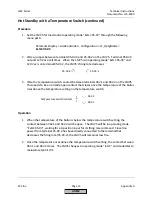
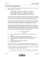
When executing a low fire hold with the RWF55, either “ExtLC X5-03” or “ExtLC X62” may be
chosen for the LMV5’s operating mode. The wiring and setup of the RWF55 differs slightly
depending on the mode selected as shown on the following pages.
HOME
Summary of Contents for LMV 5 Series
Page 2: ...Intentionally Left Blank ...
Page 41: ...LMV Series Technical Instructions Document No LV5 1000 SCC Inc Page 7 Section 2 HOME ...
Page 42: ...Technical Instructions LMV Series Document No LV5 1000 Section 2 Page 8 SCC Inc HOME ...
Page 43: ...LMV Series Technical Instructions Document No LV5 1000 SCC Inc Page 9 Section 2 HOME ...
Page 44: ...Technical Instructions LMV Series Document No LV5 1000 Section 2 Page 10 SCC Inc HOME ...
Page 45: ...LMV Series Technical Instructions Document No LV5 1000 SCC Inc Page 11 Section 2 HOME ...
Page 46: ...Technical Instructions LMV Series Document No LV5 1000 Section 2 Page 12 SCC Inc HOME ...
Page 47: ...LMV Series Technical Instructions Document No LV5 1000 SCC Inc Page 13 Section 2 HOME ...
Page 48: ...Technical Instructions LMV Series Document No LV5 1000 Section 2 Page 14 SCC Inc HOME ...
Page 49: ...LMV Series Technical Instructions Document No LV5 1000 SCC Inc Page 15 Section 2 HOME ...
Page 50: ...Technical Instructions LMV Series Document No LV5 1000 Section 2 Page 16 SCC Inc HOME ...
Page 51: ...LMV Series Technical Instructions Document No LV5 1000 SCC Inc Page 17 Section 2 HOME ...
Page 52: ...Technical Instructions LMV Series Document No LV5 1000 Section 2 Page 18 SCC Inc HOME ...
Page 53: ...LMV Series Technical Instructions Document No LV5 1000 SCC Inc Page 19 Section 2 HOME ...
Page 54: ...Technical Instructions LMV Series Document No LV5 1000 Section 2 Page 20 SCC Inc HOME ...
Page 55: ...LMV Series Technical Instructions Document No LV5 1000 SCC Inc Page 21 Section 2 HOME ...
Page 373: ...Intentionally Left Blank ...