


3. SIGNALS AND WIRING
3 - 57
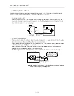
3.10 Servo motor with an electromagnetic brake
3.10.1 Safety precautions
CAUTION
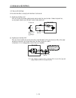
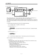
Configure an electromagnetic brake circuit so that it is activated also by an
external EMG stop switch.
Servo motor
Electromagnetic brake
B
U
RA
Contacts must be opened when ALM (Malfunction)
or MBR (Electromagnetic brake interlock) turns off.
24 V DC
Contacts must be opened with the
EMG stop switch.
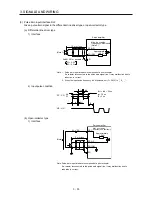
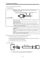
The electromagnetic brake is provided for holding purpose and must not be used
for ordinary braking.
Before operating the servo motor, be sure to confirm that the electromagnetic
brake operates properly.
Do not use the 24 V DC interface power supply for the electromagnetic brake.
Always use the power supply designed exclusively for the electromagnetic brake.
Otherwise, it may cause a malfunction.
POINT
Refer to "HF-KN/HF-SN Servo Motor Instruction Manual" for specifications such
as the power supply capacity and operation delay time of the electromagnetic
brake.
Refer to "HF-KN/HF-SN Servo Motor Instruction Manual" for the selection of a
surge absorber for the electromagnetic brake.
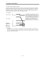
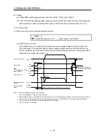
Note the following when the servo motor with an electromagnetic brake is used.
1) The brake will operate when the power (24 V DC) turns off.
2) The status is base circuit shut-off during RES (Reset) on. When you use the motor in vertical axis
system, use MBR (Electromagnetic brake interlock).
3) Turn off SON (Servo-on) after the servo motor stopped.
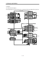
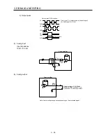
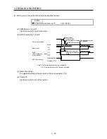
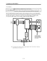
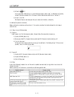
(1) Connection diagram
B2
B1
MBR
DOCOM
RA1
U
B
Servo motor
24 V DC
ALM
(Malfaunction)
Servo amplifier
MBR
RA1
(Note 1)
(Note 2)
24 V DC
Note 1. Create the circuit in order to shut off by interlocking with the emergency stop switch.
2. Do not use the 24 V DC interface power supply for the electromagnetic brake.
Summary of Contents for MELSERVO-JE MR-JE-100A
Page 23: ...1 FUNCTIONS AND CONFIGURATION 1 12 MEMO ...
Page 29: ...2 INSTALLATION 2 6 MEMO ...
Page 91: ...3 SIGNALS AND WIRING 3 62 MEMO ...
Page 171: ...5 PARAMETERS 5 44 MEMO ...
Page 195: ...6 NORMAL GAIN ADJUSTMENT 6 24 MEMO ...
Page 221: ...7 SPECIAL ADJUSTMENT FUNCTIONS 7 26 MEMO ...
Page 249: ...8 TROUBLESHOOTING 8 28 MEMO ...
Page 255: ...9 DIMENSIONS 9 6 MEMO ...
Page 263: ...10 CHARACTERISTICS 10 8 MEMO ...
Page 293: ...11 OPTIONS AND PERIPHERAL EQUIPMENT 11 30 MEMO ...


