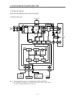
1. FUNCTIONS AND CONFIGURATION
1 - 9
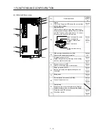
(2) MR-JE-200A or more
No.
Name/Application
Detailed
explanati
on
(1)
Display
The 5-digit, 7-segment LED shows the servo status
and the alarm number.
Section
4.5
(2)
Operation section
Used to perform status display, diagnostic, alarm,
and parameter setting operations. Push the "MODE"
and "SET" buttons at the same time for 3 s or more
to switch to the one-touch tuning mode.
Used to change the mode.
Used to change the
display or data in each
mode.
Used to set data.
To the one-touch tuning
mode
Section
4.5
Section
6.2
(3)
USB communication connector (CN3)
Connect with the personal computer.
Section
11.4
(4)
I/O signal connector (CN1)
Digital I/O signal, analog input signal, and analog
monitor output are connected.
Section
3.2
Section
3.4
(5)
Encoder connector (CN2)
Used to connect the servo motor encoder.
Section
3.4
(6)
Power connector (CNP1)
Input power supply and regenerative option are
connected.
Section
3.1
Section
3.3
(7)
Rating plate
Section
1.6
(8)
Servo motor power connector (CNP2)
Connect the servo motor.
Section
3.1
Section
3.3
(9)
Charge lamp
When the main circuit is charged, this will light up.
While this lamp is lit, do not reconnect the cables.
(1)
(2)
(6)
(7)
(8)
(9)
(10)
Bottom
Side
(4)
(5)
(3)
(10)
Protective earth (PE) terminal
Grounding terminal
Section
3.1
Section
3.3
Summary of Contents for MELSERVO-JE MR-JE-100A
Page 23: ...1 FUNCTIONS AND CONFIGURATION 1 12 MEMO ...
Page 29: ...2 INSTALLATION 2 6 MEMO ...
Page 91: ...3 SIGNALS AND WIRING 3 62 MEMO ...
Page 171: ...5 PARAMETERS 5 44 MEMO ...
Page 195: ...6 NORMAL GAIN ADJUSTMENT 6 24 MEMO ...
Page 221: ...7 SPECIAL ADJUSTMENT FUNCTIONS 7 26 MEMO ...
Page 249: ...8 TROUBLESHOOTING 8 28 MEMO ...
Page 255: ...9 DIMENSIONS 9 6 MEMO ...
Page 263: ...10 CHARACTERISTICS 10 8 MEMO ...
Page 293: ...11 OPTIONS AND PERIPHERAL EQUIPMENT 11 30 MEMO ...

