APPENDIX
App. - 11
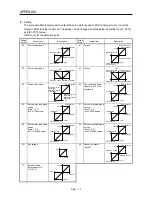
(2) Setting
The servo amplifier is factory-set to output the servo motor speed to MO1 (Analog monitor 1) and the
torque to MO2 (Analog monitor 2). The setting can be changed as listed below by setting the [Pr. PC14]
and [Pr. PC15] value.
Refer to (3) for the detection point.
Setting
value
Output item
Description
Setting
value
Output item
Description
00
Servo motor speed
Maximum speed
CW direction
CCW direction
Maximum speed
0
8 [V]
-8 [V]
01
Torque
Maximum torque
Power running in
CW direction
Power running in
CCW direction
Maximum torque
0
8 [V]
-8 [V]
02
Servo motor speed
Maximum speed
CW direction
CCW direction
Maximum speed 0
8 [V]
03
Torque
Maximum torque
Power running in
CW direction
Power running in
CCW direction
Maximum torque 0
8 [V]
04
Current command
Maximum current
command
(Maximum torque
command)
CW direction
CCW direction
Maximum current
command
(Maximum torque
command)
0
8 [V]
-8 [V]
05
The command pulse
frequency (±10 V/±4
Mpulses/s)
4 [Mpulse/s]
CW direction
CCW direction
4 [Mpulse/s]
0
10 [V]
-10 [V]
06
Servo motor-side droop
pulses
(Note 1, 2, 3)
(±10 V/100 pulses)
100 [pulse]
CW direction
CCW direction
100 [pulse]
0
10 [V]
-10 [V]
07
Servo motor-side droop
pulses
(Note 1, 2, 3)
(±10 V/1000 pulses)
1000 [pulse]
CW direction
CCW direction
1000 [pulse]
0
10 [V]
-10 [V]
08
Servo motor-side droop
pulses
(Note 1, 2, 3)
(±10 V/10000 pulses)
10000 [pulse]
CW direction
CCW direction
10000 [pulse]
0
10 [V]
-10 [V]
09
Servo motor-side droop
pulses
(Note 1, 2, 3)
(±10 V/100000 pulses)
100000 [pulse]
CW direction
CCW direction
100000 [pulse]
0
10 [V]
-10 [V]
0D
Bus voltage
400 [V]
0
8 [V]
0E
Speed command 2
(Note 2)
Maximum speed
CW direction
CCW direction
Maximum speed
0
8 [V]
-8 [V]
17
Encoder inside
temperature (±10
V/±128
˚
C)
128 [°C]
-128 [°C]
0
10 [V]
-10 [V]
Summary of Contents for MELSERVO-JE MR-JE-100A
Page 23: ...1 FUNCTIONS AND CONFIGURATION 1 12 MEMO ...
Page 29: ...2 INSTALLATION 2 6 MEMO ...
Page 91: ...3 SIGNALS AND WIRING 3 62 MEMO ...
Page 171: ...5 PARAMETERS 5 44 MEMO ...
Page 195: ...6 NORMAL GAIN ADJUSTMENT 6 24 MEMO ...
Page 221: ...7 SPECIAL ADJUSTMENT FUNCTIONS 7 26 MEMO ...
Page 249: ...8 TROUBLESHOOTING 8 28 MEMO ...
Page 255: ...9 DIMENSIONS 9 6 MEMO ...
Page 263: ...10 CHARACTERISTICS 10 8 MEMO ...
Page 293: ...11 OPTIONS AND PERIPHERAL EQUIPMENT 11 30 MEMO ...


