8. TROUBLESHOOTING
8 - 5
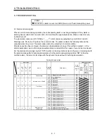
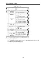
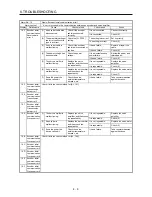
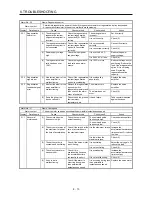
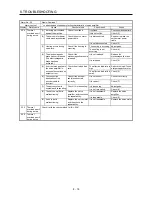
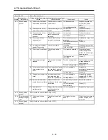
Table 8.2 Warning list
No.
Name
Detailed
display
Detail name
Stop
method
(Note 2,
3)
91
Servo amplifier overheat
warning (Note 1)
91.1
Main circuit device overheat warning
99.1
Forward rotation stroke end off
(Note 4)
Warning
99
Stroke limit warning
99.2
Reverse rotation stroke end off
(Note 4)
E0
Excessive regeneration
warning (Note 1)
E0.1
Excessive regeneration warning
E1.1
Thermal overload warning 1 during
operation
E1.2
Thermal overload warning 2 during
operation
E1.3
Thermal overload warning 3 during
operation
E1
Overload warning 1
(Note 1)
E1.4
Thermal overload warning 4 during
operation
E1.5
Thermal overload error 1 during a stop
E1.6
Thermal overload error 2 during a stop
E1.7
Thermal overload error 3 during a stop
E1.8
Thermal overload error 4 during a stop
E6
Servo forced stop warning
E6.1
Forced stop warning
SD
E8
Cooling fan speed
reduction warning
E8.1
Decreased cooling fan speed warning
E9.1
Servo-on signal on during main circuit off
DB
E9
Main circuit off warning
E9.2
Bus voltage drop during low speed
operation
DB
EC
Overload warning 2
(Note 1)
EC.1 Overload warning 2
ED
Output watt excess
warning
ED.1 Output watt excess warning
F0.1
Instantaneous power failure tough drive
warning
F0
Tough drive warning
F0.3
Vibration tough drive warning
F2.1
Drive recorder - Area writing time-out
warning
F2
Drive recorder - Miswriting
warning
F2.2
Drive recorder - Data miswriting warning
F3
Oscillation detection
warning
F3.1
Oscillation detection warning
Note 1. Leave for about 30 minutes of cooling time after removing the cause of occurrence.
2. Stop method indicates as follows:
DB: Stop with dynamic brake
SD: Forced stop deceleration
3. This is applicable when [Pr. PA04] is set to the initial value. The stop system of SD can be changed to DB using [Pr. PA04].
4. Quick stop or slow stop can be selected using [Pr. PD30].
Summary of Contents for MELSERVO-JE MR-JE-100A
Page 23: ...1 FUNCTIONS AND CONFIGURATION 1 12 MEMO ...
Page 29: ...2 INSTALLATION 2 6 MEMO ...
Page 91: ...3 SIGNALS AND WIRING 3 62 MEMO ...
Page 171: ...5 PARAMETERS 5 44 MEMO ...
Page 195: ...6 NORMAL GAIN ADJUSTMENT 6 24 MEMO ...
Page 221: ...7 SPECIAL ADJUSTMENT FUNCTIONS 7 26 MEMO ...
Page 249: ...8 TROUBLESHOOTING 8 28 MEMO ...
Page 255: ...9 DIMENSIONS 9 6 MEMO ...
Page 263: ...10 CHARACTERISTICS 10 8 MEMO ...
Page 293: ...11 OPTIONS AND PERIPHERAL EQUIPMENT 11 30 MEMO ...


