11. OPTIONS AND PERIPHERAL EQUIPMENT
11 - 7
11.2.4 Selection of regenerative option
POINT
When you use a regenerative option with an MR-JE-40A to MR-JE-100A,
remove the built-in regenerative resistor and wiring from the servo amplifier.
When MR-RB50 is used, a cooling fan is required to cool it. The cooling fan
should be prepared by the customer.
For the wire sizes used for wiring, refer to section 11.5.
A built-in regenerative resistor should not be mounted/removed frequently.
When you remount a built-in regenerative resistor, check the lead wires of the
built-in regenerative resistor for scratches or cracks.
The regenerative option generates heat of 100
˚
C higher than the ambient temperature. Fully consider heat
dissipation, installation position, wires used, etc. before installing the option. For wiring, use flame-resistant
wires or make the wires flame-resistant and keep them away from the regenerative option. Always use
twisted cables of max. 5 m length for connection with the servo amplifier.
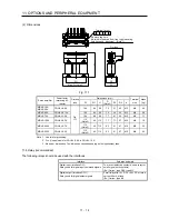
(1) MR-JE-100A or less
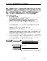
When you use a regenerative option for MR-JE-40A to MR-JE-100A, remove wirings of P+ and C,
remove the built-in regenerative resistor, and then connect the regenerative option between P+ and C.
G3 and G4 are terminals for thermal sensor. Between G3 and G4 is opened when the regenerative
option overheats abnormally.
Always remove the wiring (across P+ to C) of the
servo amplifier built-in regenerative resistor.
P+
C
G4
G3
C
P
Regenerative option
5 m or less
Servo amplifier
(Note 2)
(Note 1)
Note 1. The built-in regenerative resistor is not provided for MR-JE-10A and MR-JE-20A.
2. Make up a sequence which will switch off the magnetic contactor when abnormal
heating occurs.
G3-G4 contact specifications
Maximum voltage: 120 V AC/DC
Maximum current: 0.5 A/4.8 V DC
Maximum capacity: 2.4 VA
Summary of Contents for MELSERVO-JE MR-JE-100A
Page 23: ...1 FUNCTIONS AND CONFIGURATION 1 12 MEMO ...
Page 29: ...2 INSTALLATION 2 6 MEMO ...
Page 91: ...3 SIGNALS AND WIRING 3 62 MEMO ...
Page 171: ...5 PARAMETERS 5 44 MEMO ...
Page 195: ...6 NORMAL GAIN ADJUSTMENT 6 24 MEMO ...
Page 221: ...7 SPECIAL ADJUSTMENT FUNCTIONS 7 26 MEMO ...
Page 249: ...8 TROUBLESHOOTING 8 28 MEMO ...
Page 255: ...9 DIMENSIONS 9 6 MEMO ...
Page 263: ...10 CHARACTERISTICS 10 8 MEMO ...
Page 293: ...11 OPTIONS AND PERIPHERAL EQUIPMENT 11 30 MEMO ...

