5. PARAMETERS
5 - 36
Control mode
No./
symbol/name
Setting
digit
Function
Initial
value
[unit]
P
S
T
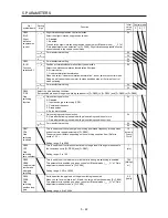
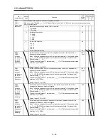
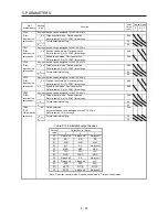
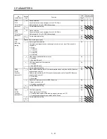
PC37
VCO
Analog speed
command
offset/Analog
speed limit
offset
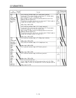
This is used to set the offset voltage of VC (Analog speed command).
For example, if CCW rotation is provided by switching on ST1 (Forward rotation
start) with applying 0 V to VC, set a negative value.
When automatic VC offset is used, the automatically offset value is set to this
parameter. (Refer to section 4.5.4.)
The initial value is provided before shipment by the automatic VC offset function on
condition that the voltage between VC and LG is 0 V.
Setting range: -9999 to 9999
The
value
differs
depend
ing on
the
servo
amplifi
ers.
[mV]
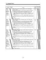
This is used to set the offset voltage of VLA (Analog speed limit).
For example, if CCW rotation is provided by switching on RS1 (Forward rotation
selection) with applying 0 V to VLA, set a negative value.
When automatic VC offset is used, the automatically offset value is set to this
parameter. (Refer to section 4.5.4.)
The initial value is provided before shipment by the automatic VC offset function on
condition that the voltage between VLA and LG is 0 V.
Setting range: -9999 to 9999
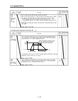
This is used to set the offset voltage of TC (Analog torque command).
Setting range: -9999 to 9999
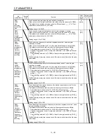
PC38
TPO
Analog torque
command
offset/Analog
torque limit
offset
This is used to set the offset voltage of TLA (Analog torque limit).
Setting range: -9999 to 9999
0
[mV]
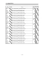
PC39
MO1
Analog
monitor 1
offset
This is used to set the offset voltage of MO1 (Analog monitor 1).
Setting range: -9999 to 9999
0
[mV]
PC40
MO2
Analog
monitor 2
offset
This is used to set the offset voltage of MO2 (Analog monitor 2).
Setting range: -9999 to 9999
0
[mV]
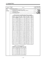
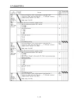
PC43
ERZ
Error
excessive
alarm level
Set an error excessive alarm level.
You can change the setting unit with "Error excessive alarm level" in [Pr. PC24].
However, setting "0" will be 3 rev. Setting over 200 rev will be clamped with 200 rev.
Setting range: 0 to 1000
0
[rev]
Summary of Contents for MELSERVO-JE MR-JE-100A
Page 23: ...1 FUNCTIONS AND CONFIGURATION 1 12 MEMO ...
Page 29: ...2 INSTALLATION 2 6 MEMO ...
Page 91: ...3 SIGNALS AND WIRING 3 62 MEMO ...
Page 171: ...5 PARAMETERS 5 44 MEMO ...
Page 195: ...6 NORMAL GAIN ADJUSTMENT 6 24 MEMO ...
Page 221: ...7 SPECIAL ADJUSTMENT FUNCTIONS 7 26 MEMO ...
Page 249: ...8 TROUBLESHOOTING 8 28 MEMO ...
Page 255: ...9 DIMENSIONS 9 6 MEMO ...
Page 263: ...10 CHARACTERISTICS 10 8 MEMO ...
Page 293: ...11 OPTIONS AND PERIPHERAL EQUIPMENT 11 30 MEMO ...

