3. SIGNALS AND WIRING
3 - 13
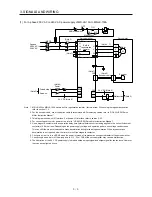
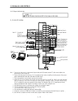
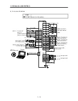
3.2.3 Torque control mode
POINT
EM2 has the same function as EM1 in the torque control mode.
(1) For sink I/O interface
Servo amplifier
(Note 6)
CN1
(Note 1)
9
(Note 2)
47
DOCOM
46
DOCOM
48
ALM
23
ZSP
4
LA
5
LAR
6
LB
7
LBR
34
LG
33
OP
SD
10 m or less
2 m or less
(Note 6)
CN1
49
RD
8
LZ
LZR
(Note 6)
CN1
20
DICOM
21
DICOM
+
CN3
27
2 m or less
28
2
TC
SD
VLA
LG
Analog torque command
±8 V/maximum torque
(Note 8) Analog speed limit
0 to ±10 V/rated speed
(Note 7)
MR Configurator2
42
15
19
41
EM2
SON
RS1
RS2
RA1
RA2
RA3
2 m or less
26
MO1
30
LG
29
MO2
± 10 V DC
± 10 V DC
SD
24 V DC (Note 4)
10 m or less
24 V DC (Note 4)
-8 V to +8 V
-10 V to +10 V
Forward rotation start
Reverse rotation start
Forced stop 2
Servo-on
(Note 3)
(Note 9)
Power supply
Plate
Plate
Plate
Ready
Malfunction (Note 6)
Zero speed detection
Encoder A-phase pulse
(differential line driver)
Encoder Z-phase pulse
(differential line driver)
Encoder B-phase pulse
(differential line driver)
Control common
Encoder Z-phase pulse
(open collector)
Analog monitor 1
Analog monitor 2
USB cable (option)
Personal
computer
Note 1. To prevent an electric shock, always connect the protective earth (PE) terminal (marked ) of the servo amplifier to the
protective earth (PE) of the cabinet.
2. Connect the diode in the correct direction. If it is connected reversely, the servo amplifier will malfunction and will not output
signals, disabling EM2 (Forced stop 2) and other protective circuits.
3. The forced stop switch (normally closed contact) must be installed.
4. Supply 24 V DC ± 10% to interfaces from outside. The total current capacity is up to 300 mA. 300 mA is the value applicable
when all I/O signals are used. The current capacity can be decreased by reducing the number of I/O points. Refer to section
3.9.2 (1) that gives the current value necessary for the interface. The illustration of the 24 V DC power supply is divided
between input signal and output signal for convenience. However, they can be configured by one.
5. ALM (Malfunction) turns on in normal alarm-free condition (normally closed contact).
6. The pins with the same signal name are connected in the servo amplifier.
7. Use SW1DNC-MRC2-E. (Refer to section 11.4.)
8. Use an external power supply when inputting a negative voltage.
9. Configure a circuit to turn off EM2 when the power is turned off to prevent an unexpected restart of the servo amplifier.
10. Plus and minus of the power of source interface are the opposite of those of sink interface.
Summary of Contents for MELSERVO-JE MR-JE-100A
Page 23: ...1 FUNCTIONS AND CONFIGURATION 1 12 MEMO ...
Page 29: ...2 INSTALLATION 2 6 MEMO ...
Page 91: ...3 SIGNALS AND WIRING 3 62 MEMO ...
Page 171: ...5 PARAMETERS 5 44 MEMO ...
Page 195: ...6 NORMAL GAIN ADJUSTMENT 6 24 MEMO ...
Page 221: ...7 SPECIAL ADJUSTMENT FUNCTIONS 7 26 MEMO ...
Page 249: ...8 TROUBLESHOOTING 8 28 MEMO ...
Page 255: ...9 DIMENSIONS 9 6 MEMO ...
Page 263: ...10 CHARACTERISTICS 10 8 MEMO ...
Page 293: ...11 OPTIONS AND PERIPHERAL EQUIPMENT 11 30 MEMO ...

