3. SIGNALS AND WIRING
3 - 30
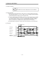
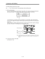
The following section explains about the case where the negative logic and the forward/reverse
rotation pulse trains are set to "_ _ 1 0" in [Pr. PA13].
Reverse rotation command
Forward rotation command
(OFF)
(OFF)
(OFF)
(ON)
(ON)
(ON) (OFF) (ON) (OFF) (ON)
(OFF)
Forward rotation pulse train
(transistor)
Reverse rotation pulse train
(transistor)
(ON)
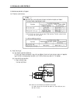
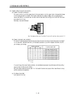
2) Differential line driver type
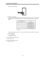
Connect as follows.
PP
NP
Servo amplifier
PG
NG
SD
Approximately
100
˖
Approximately
100
˖
(Note)
Note. Pulse train input interface is comprised of a photocoupler.
If a resistor is connected to the pulse train signal line, it may malfunction due to
reduction in current.
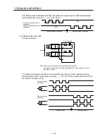
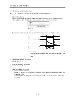
The following example shows that an input waveform has been set to the negative logic and
forward/reverse rotation pulse trains by setting "_ _ 1 0" in [Pr. PA13]. The waveforms of PP, PG,
NP, and NG are based on LG.
Reverse rotation
PP
PG
NP
NG
Reverse rotation
pulse train
Forward rotation
pulse train
Forward rotation
Summary of Contents for MELSERVO-JE MR-JE-100A
Page 23: ...1 FUNCTIONS AND CONFIGURATION 1 12 MEMO ...
Page 29: ...2 INSTALLATION 2 6 MEMO ...
Page 91: ...3 SIGNALS AND WIRING 3 62 MEMO ...
Page 171: ...5 PARAMETERS 5 44 MEMO ...
Page 195: ...6 NORMAL GAIN ADJUSTMENT 6 24 MEMO ...
Page 221: ...7 SPECIAL ADJUSTMENT FUNCTIONS 7 26 MEMO ...
Page 249: ...8 TROUBLESHOOTING 8 28 MEMO ...
Page 255: ...9 DIMENSIONS 9 6 MEMO ...
Page 263: ...10 CHARACTERISTICS 10 8 MEMO ...
Page 293: ...11 OPTIONS AND PERIPHERAL EQUIPMENT 11 30 MEMO ...

