APPENDIX
App. - 7
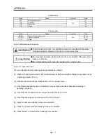
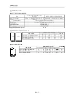
Output device
Symbol
Device
Connector
Pin No.
ZSP
Zero speed detection
23
INP
In-position
24
ALM
Malfunction
CN1
48
RD
Ready
49
Power supply
Symbol
Device
Connector
Pin No.
DICOM
Digital I/F power supply input
20, 21
DOCOM
Digital I/F common
CN1
46, 47
SD
Shield
Plate
App. 2.5 Maintenance and service
WARNING
To avoid an electric shock, only qualified personnel should attempt inspections.
For repair and parts replacement, contact your local sales office.
CAUTION
Do not perform insulation resistance test on the servo amplifier. Otherwise, it may
cause a malfunction.
Do not disassemble and/or repair the equipment on customer side.
App. 2.5.1 Inspection items
It is recommended that the following points periodically be checked.
(1) Check for loose protective earth (PE) terminal screws of the servo amplifier. Retighten any loose screws.
(Tightening torque: 1.2 N•m)
(2) Check servo motor bearings, brake section, etc. for unusual noise.
(3) Check the cables and the like for scratches or cracks. Perform periodic inspection according to
operating conditions.
(4) Check that the connectors are securely connected to the servo motor.
(5) Check that the wires are not coming out from the connector.
(6) Check for dust accumulation on the servo amplifier.
(7) Check for unusual noise generated from the servo amplifier.
(8) Check the servo motor shaft and coupling for connection.
Summary of Contents for MELSERVO-JE MR-JE-100A
Page 23: ...1 FUNCTIONS AND CONFIGURATION 1 12 MEMO ...
Page 29: ...2 INSTALLATION 2 6 MEMO ...
Page 91: ...3 SIGNALS AND WIRING 3 62 MEMO ...
Page 171: ...5 PARAMETERS 5 44 MEMO ...
Page 195: ...6 NORMAL GAIN ADJUSTMENT 6 24 MEMO ...
Page 221: ...7 SPECIAL ADJUSTMENT FUNCTIONS 7 26 MEMO ...
Page 249: ...8 TROUBLESHOOTING 8 28 MEMO ...
Page 255: ...9 DIMENSIONS 9 6 MEMO ...
Page 263: ...10 CHARACTERISTICS 10 8 MEMO ...
Page 293: ...11 OPTIONS AND PERIPHERAL EQUIPMENT 11 30 MEMO ...

