CAN Controller
UG0331 User Guide Revision 15.0
436
12
CAN Controller
SmartFusion2 SoC FPGAs contain an integrated control area network (CAN) peripheral. The CAN
controller is an advanced peripheral bus (APB_1) slave on the MSS AHB bus matrix. Refer to the
page 210 for a detailed description. A master such as the Cortex-M3 processor or a master
in the FPGA fabric configures the CAN controller through the APB slave.
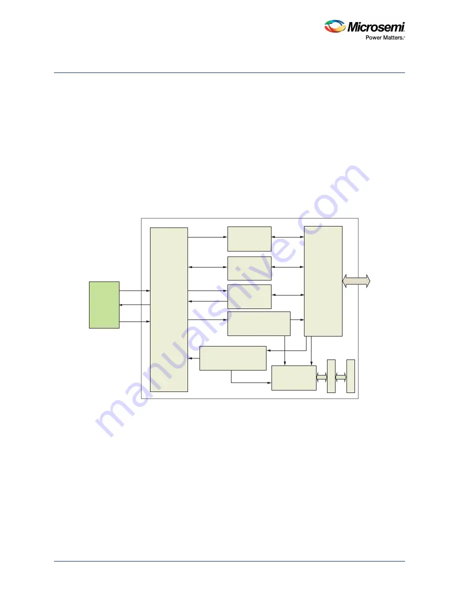
The CAN controller in the SmartFusion2 device supports the concept of mailboxes. It is compliant to the
international CAN standard defined in ISO 11898-1. It contains 32 receive buffers. Each buffer has its
own message filter and 32 transmit buffers with prioritized arbitration scheme. For optimal support of
higher-layer protocols (HLP) such as DeviceNet, the message filter also covers the first two data bytes of
the message payload. A block diagram of the CAN controller is shown in the following figure. Transmit
and receive message buffers are single error corrected, double error detected (SECDED) through the
error detection and correction (EDAC) controller. The functional behavior of the CAN instance must be
defined at the application level using the SmartFusion2 MSS CAN firmware driver provided by
Microsemi. Refer to the
CAN Firmware Driver User Guide
for more details.
Figure 166 •
CAN Controller Block Diagram
12.1
Features
12.1.1
Compliance
•
Full CAN 2.0A and 2.0B compliant
•
Conforms to ISO 11898-1
12.1.2
Receive Path
•
32 receive buffers
•
Each buffer has its own message filter
•
Message filter covers: ID, IDE, remote transmission request (RTR), data byte 1, and data byte 2
•
Message buffers can be linked together to build a bigger message array.
•
Automatic RTR response handler with optional generation of RTR interrupt
External
Transceiver
Chip
RX
TX
TX_EN_N
Interrupt
Controller
Status and
Configuration
Control and
Command
APB Slave
Interface
Receive Message
Handler
Transmit Message
Handler
EDAC
RAM I/F
APB_1 Bus
CAN Framer
Memory Arbiter


