


6
5
KEB COMBIVERT F4-F
10
Name: Basis
11.05.99
Chapter
Section
Page
Date
©
KEB Antriebstechnik, 1999
All Rights reserved
Functional Description
Motor Data and Controller Adjustment
6.5.13 Speed Control
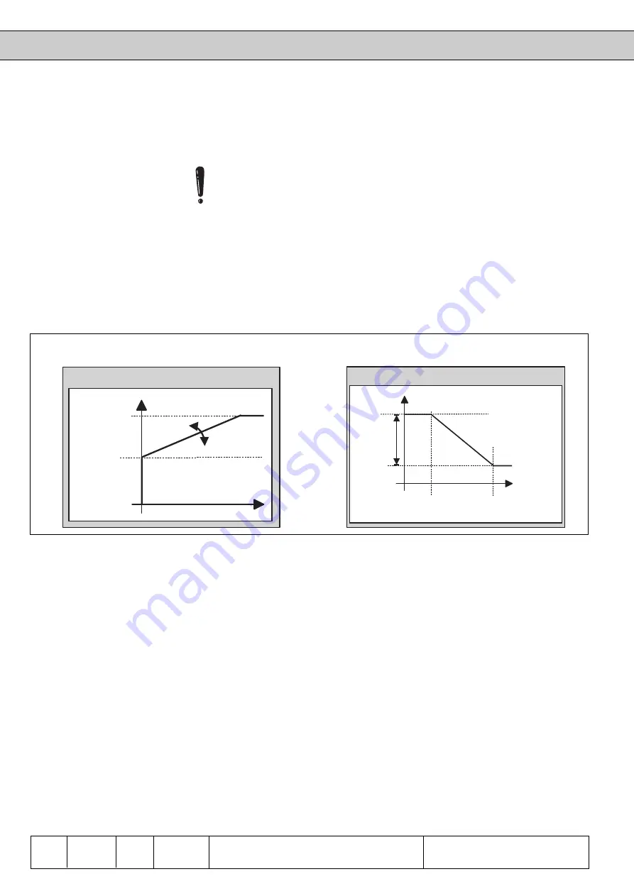
The speed controller consists of a PI-controller, at which the P-factor is system-
deviation-dependent (see picture A) and the I-factor is speed-dependent (see pictur B).
The torque limits can be adjusted separately for all 4 quadrants.
The limits take effect without hysteresis and without ramp immediately, for that
reason different settings can result in torque jumps at a change of the quadrant.
The proportional factor of the speed controller is adjusted in these parameters. In
addition to the standard KP-value a system-deviation-dependent proportional gain
can be adjusted with CS.3 and CS.4. With it the dynamic performance can be improved
and overshootings can be dampened.
CS.3 defines to what extent the control deviation effects the proportional factor. CS.4
limits the proportional factor.
Exception: If the standard KP-value (CS.0) is larger than the limit value CS.4, then
the proportional factor is = CS.0.
These parameters define the integral factor of the speed controller. To achieve a
better speed rigidity at small speed and in standstill the KI-factor can be varied in
dependence on the speed (CS.12, CS.13).
• CS. 1 forms the base value
• the maximum KI-value is CS. 1 + CS. 11
• the two corner speeds CS.12 and CS.13 define in which speed range the KI-
value is changed
These parameters define the torque limits in the 4 quadrants.
KP speed(CS.0)
KP speed gain (CS.3)
KP speed limit (CS.4)
KI speed(CS. 1)
KI offset (CS.11)
Corner speed max. KI (CS.12)
Corner Speed standard KI
(CS.13)
Fig. 6.5.13 Mode of functioning of the speed controller
Picture A
Picture B
To improve the standstill rigiditiy of the drive a standstill position control can be adjusted.
The position control becomes active when actual and setpoint speed have reached
the value 0 min
-1
. The position control is deactivated as soon as the setpoint speed
has reached a value of <> 0 min
-1
or when the control release is not given.
The setpoint position, onto which the drive controls, is the position value at which the
condition actual and setpoint speed=0 min
-1
exists for the first time (at given control
release).
The maximum displacement of the motor may not exeed a half revolution. If the motor
is diplaced further the setpoint position changes by a complete motor revolution (=>
position setpoint jump).
At SP.00 = 18 (direct setpoint setting) the position controller cannot be activated. In
the positioning module (Pc.0 = 1) the position standstill controller cannot be activated.
The proportional factor of the position controller is adjusted in CS.14. A value of 0
deactivates the controller. The definition of the setpoint position takes place at
deactivated controller too.
Standstill position control
(CS.14)
Kp speed
limit [CS. 4]
Kp speed
[CS. 0]
Kp speed
amplification
[CS. 3]
Kp speed
Xd(n)
Kp speed fact calculation
Ki speed fact calculation
Max. Ki
increase
[CS.11]
Ki speed
[CS. 1]
Max. speed
for max. Ki
[CS.12]
Min. speed for
standard Ki
[CS.13]
actual speed
Ki speed