Basic Configuration
172
1
Select
Eng Setup, Outputs
in the menu.
2
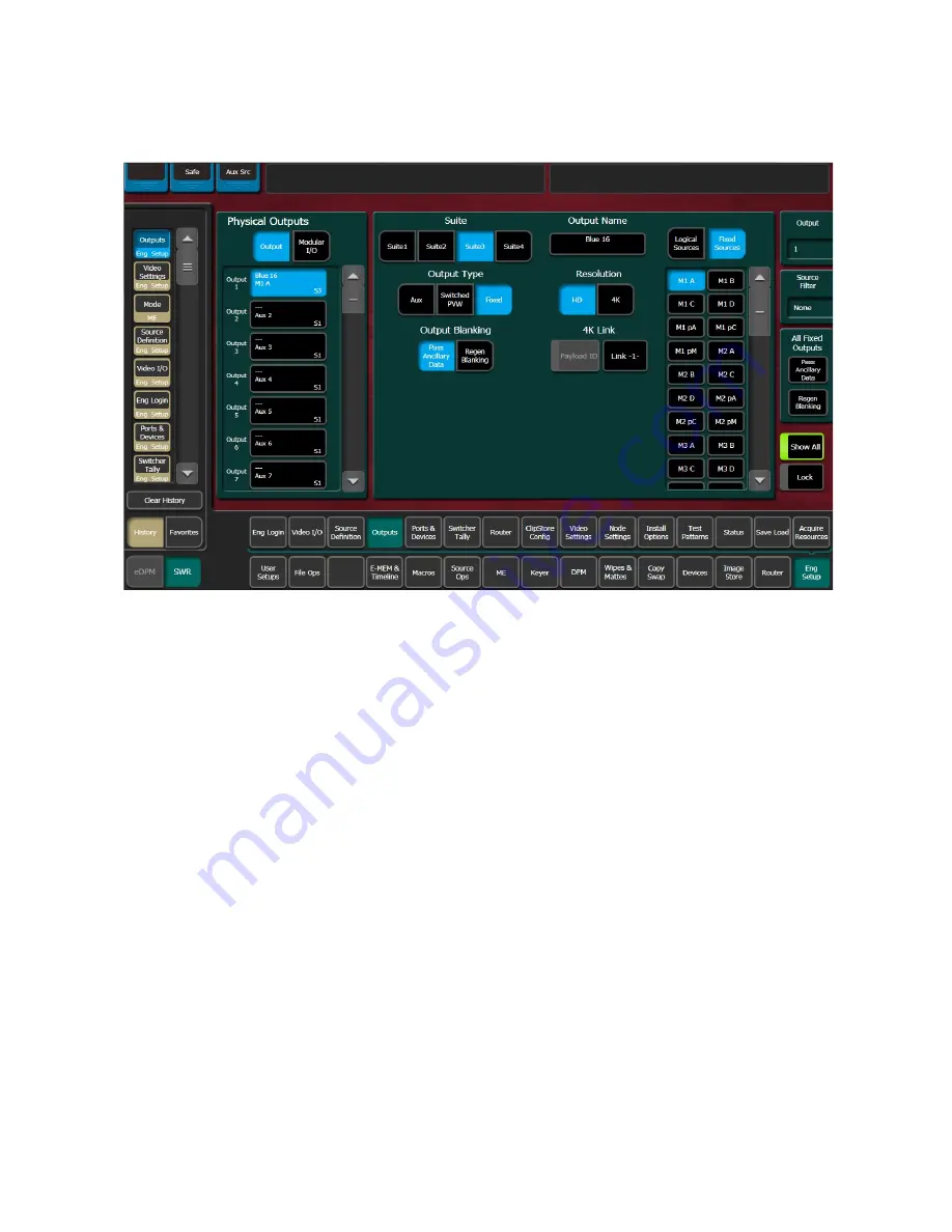
Select an output data pad from the left scrolling list to select it and display information
for that output connector.
3
Select the appropriate Output Type:
a
Fixed
if the output is to be dedicated. Later you will be able to select from either
Logical Sources or Fixed Sources for that output.
b
Switched PVW
if the output will be used for switched preview. Switched preview
can be assigned to multiple outputs.
c
Aux
if the output will be an Aux bus.
The
Suite 1
through
Suite 4
buttons are used to assign the currently selected output to a
suite. The default setting is
Suite 1
.
4
Select an output connector from the list on the right. The change is immediate and can
be viewed on a connected monitor. (Switched Preview mode does not offer any output
sources).
5
If desired, select the
Output Name
data pad to change the name of the output using
the pop up alphanumeric keypad or standard keyboard. This name appears on the data
pad of the scrolling list on the left. Up to 12 characters can be entered.
Summary of Contents for KARRERA
Page 47: ...Installation Service Manual 23 15 RU Dimensions Side View ...
Page 49: ...Installation Service Manual 25 15RUVideo Processor Views 15 RU Front View withDoor Removed ...
Page 50: ...Frame Installation 26 15 RU Rear ViewIP Gearbox Conversion 15RU Front View withDoor Removed ...
Page 52: ...Frame Installation 28 PowerSupplyFrameDimensions TopView ...
Page 171: ...Installation Service Manual 147 ...
Page 204: ...Basic Configuration 180 ...
Page 208: ...Basic Configuration 184 green ...
Page 234: ...Basic Configuration 210 ...
Page 265: ...Installation Service Manual 241 ...
Page 296: ...External Interfaces 272 PBus and GPI Enables ...
Page 366: ...Maintenance 342 ...
Page 367: ...Installation Service Manual 343 ...
Page 368: ...Maintenance 344 ...


