3–20
850 FEEDER PROTECTION SYSTEM – INSTRUCTION MANUAL
FRONT CONTROL PANEL INTERFACE
CHAPTER 3: INTERFACES
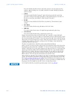
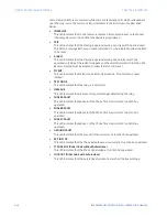
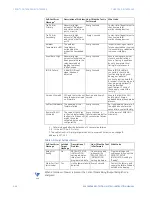
Table 3-9: Major Self-test Errors
N
OTE
NOTE:
When a total loss of power is present, the Critical Failure Relay (Output Relay 8) is de-
energized.
Traffic Error
Primary
Abnormally high
amount of Broadcast
and Uni-cast traffic on
port 1 or port 4
Every 1 second
Contact site IT department to
check network for
malfunctioning devices
Traffic Error
Secondary
Abnormally high
amount of Broadcast
and Uni-cast traffic on
port 5
Every 1 second
Contact site IT department to
check network for
malfunctioning devices
Ambient
Temperature >80C
The ambient
temperature
surrounding the
product has exceeded
80C
Every 1 second
Inspect mounting enclosure
for unexpected heat sources
(i.e loose primary cables) and
remove accordingly
Event Rate High
Abnormally high
amounts of events have
been generated so the
relay has stopped
logging to prevent
further issues
Every 1 second
Ensure settings are not set
close to nominal ratings.
Ensure FlexLogic equations
do not have impractical
timing for status events
IRIG-B Failure
A bad IRIG-B input
signal has been
detected
Every 1 second
Ensure IRIG-B cable is
connected, check cable
functionality (i.e. physical
damage or perform
continuity test), ensure IRIG-
B receiver is functioning, and
check input signal level (it
may be less than
specification). If none of
these apply, contact the
factory.
Version Mismatch CPU and Comms do not
have the same revision
on firmware
Boot-up and Every 1
second
Ensure that both the CPU
and Comms FW was
uploaded during the upgrade
process
SelfTestFWUpdate The updating of the
firmware failed
Every 1 second
Re-try uploading firmware. If
the upload doesn’t work a
second time contact factory
Remote CAN IO
Mismatch
The value of the cards
in the slots detected by
the Remote IO does not
match the value
validated by the user
configuration
Every 1 second. A
failure is declared after
60 consecutive failures
Fix the remote CANBUS IO
mismatch.
1. – Failure is logged after the detection of 5 consecutive failures
2. $ – is the slot ID (i.e., F, G, H etc.)
3.To disable Link Error Primary target when not in-use with SE order code, change IP
address to 127.0.0.1
Self-test Error
Message
Latched
Target
Message
Description of
Problem
How Often the Test
is Performed
What to do
Relay Not
Ready
No
PRODUCT SETUP
INSTALLATION
setting indicates
relay is not in a
programmed state.
On power up and
whenever the
PRODUCT SETUP
INSTALLATION
setting is altered.
Program all required
settings and then set the
PRODUCT SETUP
INSTALLATION setting to
“Ready”.
Major Self-Test
(error code)
Yes
Unit hardware failure
detected
Every 1 second
Contact the factory and
supply the failure code as
noted on the display.
Self-test Error
Message
1
Description of Problem How Often the Test is
Performed
What to do
Summary of Contents for Multilin 850
Page 10: ...VIII 850 FEEDER PROTECTION SYSTEM INSTRUCTION MANUAL ...
Page 135: ...CHAPTER 3 INTERFACES SOFTWARE INTERFACE 850 FEEDER PROTECTION SYSTEM INSTRUCTION MANUAL 3 41 ...
Page 151: ...CHAPTER 3 INTERFACES SOFTWARE INTERFACE 850 FEEDER PROTECTION SYSTEM INSTRUCTION MANUAL 3 57 ...
Page 153: ...CHAPTER 3 INTERFACES SOFTWARE INTERFACE 850 FEEDER PROTECTION SYSTEM INSTRUCTION MANUAL 3 59 ...
Page 439: ...CHAPTER 7 MONITORING FUNCTIONS 850 FEEDER PROTECTION SYSTEM INSTRUCTION MANUAL 7 19 ...
Page 644: ...11 20 850 FEEDER PROTECTION SYSTEM INSTRUCTION MANUAL FLEXELEMENTS CHAPTER 11 METERING ...

