9–26
850 FEEDER PROTECTION SYSTEM – INSTRUCTION MANUAL
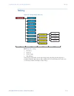
TESTING
CHAPTER 9: FLEXLOGIC AND OTHER SETPOINTS
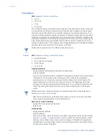
Simulation
Path:
Setpoints > Testing > Simulation
•
Setup
•
Pre-Fault
•
Fault
•
Post-Fault
The Simulation feature is provided for testing the functionality of the 8 Series in response
to programmed conditions, without the need of external AC voltage and current inputs.
First time users will find this to be a valuable training tool. System parameters such as
currents, voltages and phase angles are entered as setpoints. When placed in simulation
mode, the relay suspends reading actual AC inputs, generates samples to represent the
programmed phasors, and loads these samples into the memory to be processed by the
relay. Normal (pre-fault), fault and post-fault conditions can be simulated to exercise a
variety of relay features. There are three sets of input parameters used during simulation,
each provides a particular state of the system as follows.
NOTE
NOTE:
All Simulation setpoints revert to default values at power-up.
Setup
Path:
Setpoints > Testing > Simulation > Setup
•
Simulation State
•
Pre-Fault to Fault Trigger
•
Force Relays
•
Force LEDs
SIMULATION STATE
Range: Disabled, Prefault State, Fault State, Postfault State
Default: Disabled
Program the Simulation State to “Disabled” if actual system inputs are to be monitored.
If programmed to any other value, the relay is in test mode and actual system
parameters are not monitored, including Current, Voltage, and Contact Inputs. The
system parameters simulated by the relay are those in the following section that
correspond to the programmed value of this setpoint. For example, if programmed to
“Fault”, then the system parameters are set to those defined by the Fault setpoint
values.
NOTE
NOTE:
While in test mode, Contact Input states are automatically forced to the values set in
Setpoints > Testing > Contact Inputs
.
When the Fault State is set as the Simulation State and a Trip occurs, the Simulation
State automatically transitions to the Postfault State.
PRE-FAULT TO FAULT TRIGGER
Range: Off, On, Any FlexLogic Operand
Default: Off
FORCE RELAYS
Range: Disabled, Enabled
Default: Disabled
When in test mode, and Force Relays is “Enabled”, relay states can be forced from the
Setpoints > Testing > Output Relays
menu, this overrides the normal operation of the
output contacts. When in test mode, and Force Relays is “Disabled”, the relay states
maintain their normal operation. Forcing of output relay states is not performed when
the Simulation State is “Disabled”.
Summary of Contents for Multilin 850
Page 10: ...VIII 850 FEEDER PROTECTION SYSTEM INSTRUCTION MANUAL ...
Page 135: ...CHAPTER 3 INTERFACES SOFTWARE INTERFACE 850 FEEDER PROTECTION SYSTEM INSTRUCTION MANUAL 3 41 ...
Page 151: ...CHAPTER 3 INTERFACES SOFTWARE INTERFACE 850 FEEDER PROTECTION SYSTEM INSTRUCTION MANUAL 3 57 ...
Page 153: ...CHAPTER 3 INTERFACES SOFTWARE INTERFACE 850 FEEDER PROTECTION SYSTEM INSTRUCTION MANUAL 3 59 ...
Page 439: ...CHAPTER 7 MONITORING FUNCTIONS 850 FEEDER PROTECTION SYSTEM INSTRUCTION MANUAL 7 19 ...
Page 644: ...11 20 850 FEEDER PROTECTION SYSTEM INSTRUCTION MANUAL FLEXELEMENTS CHAPTER 11 METERING ...


