


3–50
850 FEEDER PROTECTION SYSTEM – INSTRUCTION MANUAL
SOFTWARE INTERFACE
CHAPTER 3: INTERFACES
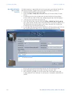
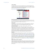
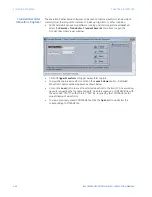
Metering Objects
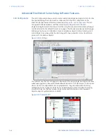
The metering objects consist of metering elements. Up to 15 metering elements can be
configured per SLD page. The metering object has an input for all the available FlexAnalog
values. The units for these values are dynamically scaled as per the defaults. The following
figure shows the metering element on a configured SLD.
Figure 3-26: Metering Element on configured SLD
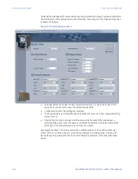
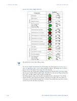
Device Status Object
The configurable SLD feature in the 8 Series allows only one device status object per SLD
page. The device status does not have any properties. It is simply shown as “Status: [device
status]”. This object shows if the breaker is opened/closed.
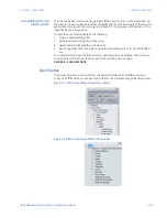
Static Objects
Static objects are used as simple bitmap images or text/drawing blocks to complete the
single line diagram. There is no control associated with these static objects. The static
objects consist of drawing tools, text object, and power system components.
Front Panel Interaction
8 Series relays use the Select-Before-Operate (SBO) mechanism for local control of
breakers and switches [IEC 61850-7-2]. Initially, the diagram can be browsed through all
available breakers and switches by using the navigation keys. After navigation, selection
must be made for the breaker or switch object by pressing the Enter key. After selecting
the desired switch or breaker, control operations can then be carried out on the selected
switch or breaker. The 8 Series allows local opening, closing, tagging, blocking, and
bypassing. Front panel control is only allowed when the relay is in Local Mode.
Navigation
The Single Line Diagram can be accessed in two ways from the front panel of the relay.
The original location for the SLD pages is under
Status > Summary > Single Line Diagram >
SLD [X]
. However, a more convenient way to access an SLD page is by setting it as a default
home screen at
Setpoints > Device > Front Panel > Home Screens > Home Screen1
. Pressing
home button more than once rotates through the configured home screens. If the desired
SLD is set to home screen 2 through home screen 10, it can be activated by pressing home
button until it appears on the screen. If no home screen is configured, the default screens
become active. If the default screens are disabled,
Status > Summary > Values
screen is
shown.
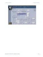
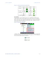
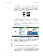
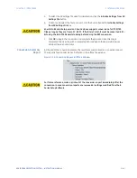
Breaker/Switch Browsing and Selection
While in the SLD screen, only one page is active at any point of time. If SLD1 is active, only
breakers and switches on SLD1 can be operated and controlled. By default, when entering
the SLD menu, the screen displays SLD1. SLD2 through SLD6 can be accessed through the
navigation pushbuttons as shown in the following figure: Active element selection with
flash message.
Summary of Contents for Multilin 850
Page 10: ...VIII 850 FEEDER PROTECTION SYSTEM INSTRUCTION MANUAL ...
Page 135: ...CHAPTER 3 INTERFACES SOFTWARE INTERFACE 850 FEEDER PROTECTION SYSTEM INSTRUCTION MANUAL 3 41 ...
Page 151: ...CHAPTER 3 INTERFACES SOFTWARE INTERFACE 850 FEEDER PROTECTION SYSTEM INSTRUCTION MANUAL 3 57 ...
Page 153: ...CHAPTER 3 INTERFACES SOFTWARE INTERFACE 850 FEEDER PROTECTION SYSTEM INSTRUCTION MANUAL 3 59 ...
Page 439: ...CHAPTER 7 MONITORING FUNCTIONS 850 FEEDER PROTECTION SYSTEM INSTRUCTION MANUAL 7 19 ...
Page 644: ...11 20 850 FEEDER PROTECTION SYSTEM INSTRUCTION MANUAL FLEXELEMENTS CHAPTER 11 METERING ...