


6–130
850 FEEDER PROTECTION SYSTEM – INSTRUCTION MANUAL
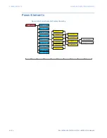
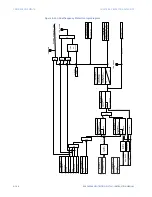
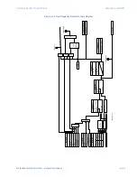
POWER ELEMENTS
CHAPTER 6: PROTECTION SETPOINTS
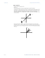
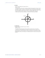
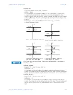
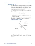
region along the RCA line. Refer to the Directional power sample applications figure for
details. Together with the RCA, this setting enables a wide range of operating
characteristics.
The setting applies to three-phase power and the rated power is as follows:
Rated Power = 3 x VT
Secondary (phase-neutral)
x VT
Ratio
x CT
Primary
(Wye-connected VT), or
Rated Power = (3)
1/2
x VT
Secondary (phase-phase)
x VT
Ratio
x CT
Primary
(Delta-connected VT)
For example:
A setting of 2% for a 200 MW machine is 0.02 × 200 MW = 4 MW. If 7.967 kV is a primary
VT phase-neutral voltage and 10 kA is a primary CT current, the source rated power is
239 MVA, and, SMIN must be set at 4 MW/239 MVA =0.0167 x Rated
≈
0.017 x Rated. If
the reverse power application is considered, RCA = 180° and SMIN = 0.017 x Rated.
The element drops out if the magnitude of the positive-sequence current becomes
virtually zero, that is, it drops below the cutoff level.
STAGE 1 DELAY
Range: 0.000 to 6000.000 s in steps of 0.001 s
Default: 0.500 s
The setting specifies a time delay for stage 1. For reverse power or low forward power
applications for a synchronous machine, stage 1 is typically applied for alarming and
stage 2 for tripping.
STAGE 2 SMIN
Range: -1.200 to 1.200 x Rated Power in steps of 0.001 x Rated Power
Default: 0.100 x Rated Power
The setting specifies the minimum power as defined along the relay characteristic angle
(RCA) for stage 2 of the element. The setting needs to be coordinated with the setting of
stage 1.
STAGE 2 DELAY
Range: 0.000 to 6000.000 s in steps of 0.001 s
Default: 20.000 s
The setting specifies a time delay for stage 2. For reverse power or low forward power
applications for a synchronous machine, stage 1 is typically applied for alarming and
stage 2 for tripping.
BLOCK
Range: Off, Any FlexLogic operand
Default: Off
OUTPUT RELAY X
For details see
EVENTS
Range: Enabled, Disabled
Default: Enabled
TARGETS
Range: Self-reset, Latched, Disabled
Default: Self-reset
Summary of Contents for Multilin 850
Page 10: ...VIII 850 FEEDER PROTECTION SYSTEM INSTRUCTION MANUAL ...
Page 135: ...CHAPTER 3 INTERFACES SOFTWARE INTERFACE 850 FEEDER PROTECTION SYSTEM INSTRUCTION MANUAL 3 41 ...
Page 151: ...CHAPTER 3 INTERFACES SOFTWARE INTERFACE 850 FEEDER PROTECTION SYSTEM INSTRUCTION MANUAL 3 57 ...
Page 153: ...CHAPTER 3 INTERFACES SOFTWARE INTERFACE 850 FEEDER PROTECTION SYSTEM INSTRUCTION MANUAL 3 59 ...
Page 439: ...CHAPTER 7 MONITORING FUNCTIONS 850 FEEDER PROTECTION SYSTEM INSTRUCTION MANUAL 7 19 ...
Page 644: ...11 20 850 FEEDER PROTECTION SYSTEM INSTRUCTION MANUAL FLEXELEMENTS CHAPTER 11 METERING ...