


CHAPTER 3: INTERFACES
SOFTWARE INTERFACE
850 FEEDER PROTECTION SYSTEM – INSTRUCTION MANUAL
3–47
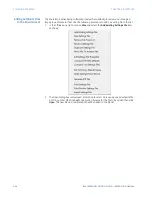
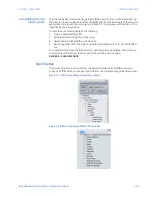
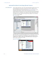
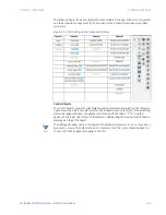
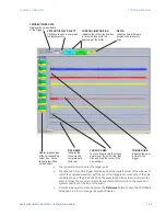
The following figure shows the objects that are available for design in the SLD Configurator
and their maximum usage limits [X]. The maximum limit reflects the maximum possible
order code.
Figure 3-22: SLD Configurator Component Library
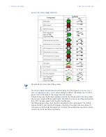
Control Objects
The control objects consist of selectable breakers and disconnect switches. The following
figure shows the different symbols in the GE Standard style and IEC style. If the switching
element is tagged, blocked, or bypassed, indicators with the letters “T”, “B”, and “By”
appear on the lower right corner of the element. Additionally, the breaker/switch name is
displayed on top of the object.
N
OTE
NOTE:
The displayed breaker name is configured in the setpoint
Setpoints > System > Breakers >
Breaker[X] > Name
. This setpoint has a 13-character limit. The name should be kept to a
minimum so that it appears properly on the SLD.
Summary of Contents for Multilin 850
Page 10: ...VIII 850 FEEDER PROTECTION SYSTEM INSTRUCTION MANUAL ...
Page 135: ...CHAPTER 3 INTERFACES SOFTWARE INTERFACE 850 FEEDER PROTECTION SYSTEM INSTRUCTION MANUAL 3 41 ...
Page 151: ...CHAPTER 3 INTERFACES SOFTWARE INTERFACE 850 FEEDER PROTECTION SYSTEM INSTRUCTION MANUAL 3 57 ...
Page 153: ...CHAPTER 3 INTERFACES SOFTWARE INTERFACE 850 FEEDER PROTECTION SYSTEM INSTRUCTION MANUAL 3 59 ...
Page 439: ...CHAPTER 7 MONITORING FUNCTIONS 850 FEEDER PROTECTION SYSTEM INSTRUCTION MANUAL 7 19 ...
Page 644: ...11 20 850 FEEDER PROTECTION SYSTEM INSTRUCTION MANUAL FLEXELEMENTS CHAPTER 11 METERING ...