8–98
850 FEEDER PROTECTION SYSTEM – INSTRUCTION MANUAL
CT SUPERVISION
CHAPTER 8: CONTROL
CT Supervision
A CT Failure, an open CT secondary wire, or a loose connection on one phase of the 3-
phase CT bank wiring may result in no current getting to one of the phases of the relay.
This may lead to misinterpretations due to a rise in negative and zero sequence current
quantities. Some of the key elements that can be affected are differential protection,
restricted ground fault, neutral overcurrent, and negative sequence instantaneous
elements. The CT Supervision function is designed to detect problems with current
transformers before other elements have a chance to trip on false current signal
information.
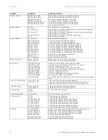
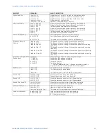
The 850 relay provides a CT Supervision element that uses three distinct checks that can
be enabled or disabled individually once the overall function is enabled. These three
checks are sequence check, differential check, and symmetry check.
The sequence check is the first check and should ideally be used for CT supervision. The
sequence check uses zero sequence current, zero sequence voltage, and ground current.
This check may not be an option if the ground current is not available, voltages are not
available, or not connected in wye configuration to be able to calculate zero sequence
voltage. If voltages are not available or they are available but in delta configuration, the
differential check can be used.
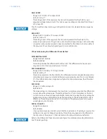
The differential check uses calculated zero sequence current and ground current to
calculate differential current. If ground current is not available, the symmetry check can
be used.
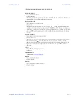
The symmetry check operates by calculating a quotient or a ratio of minimum current
over maximum current and comparing against a threshold. This function should be set
appropriately considering possible minimum and maximum load currents occurred in
various scenarios.
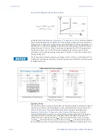
To further enhance the security of these functions and not block overcurrent in case of
fault events, an additional maximum load current supervision is added where the
maximum of the phase current magnitudes
I
max
must be less than the maximum load
current
I
Lmax
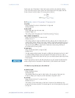
Sequence Check
In a normal balanced condition, the zero sequence and negative sequence components
are absent or within tolerances. When one of the phases of current disappears, the zero
sequence component of both voltages and currents are checked along with the measured
ground current. If the zero sequence current magnitude
3I
0
is above the pickup value and
either of
3V
0
or Ig is above the pickup value, the element is not under a CT failure condition.
If the
3I
0
is higher than pickup and neither of
3V
0
or Ig are higher than the pickup, the
element is in CT failure condition.
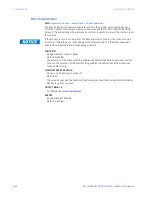
NOTE
NOTE:
All CT supervision uses J2-3V
0
for the sequence check.
Summary of Contents for Multilin 850
Page 10: ...VIII 850 FEEDER PROTECTION SYSTEM INSTRUCTION MANUAL ...
Page 135: ...CHAPTER 3 INTERFACES SOFTWARE INTERFACE 850 FEEDER PROTECTION SYSTEM INSTRUCTION MANUAL 3 41 ...
Page 151: ...CHAPTER 3 INTERFACES SOFTWARE INTERFACE 850 FEEDER PROTECTION SYSTEM INSTRUCTION MANUAL 3 57 ...
Page 153: ...CHAPTER 3 INTERFACES SOFTWARE INTERFACE 850 FEEDER PROTECTION SYSTEM INSTRUCTION MANUAL 3 59 ...
Page 439: ...CHAPTER 7 MONITORING FUNCTIONS 850 FEEDER PROTECTION SYSTEM INSTRUCTION MANUAL 7 19 ...
Page 644: ...11 20 850 FEEDER PROTECTION SYSTEM INSTRUCTION MANUAL FLEXELEMENTS CHAPTER 11 METERING ...


