


CHAPTER 8: CONTROL
POLE DISCORDANCE (52)
850 FEEDER PROTECTION SYSTEM – INSTRUCTION MANUAL
8–19
Pole Discordance (52)
Introduction
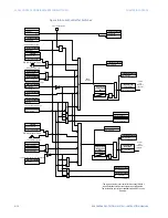
The 850-D (Distribution Feeder) relay provides three Pole Discordance elements under the
Control menu. Each element can be used for re-tripping the breaker after pole discordance
detection, or tripping an upstream breaker in cases when the pole discordance persists.
The element detects if one or two of the breaker poles remain open following a close
command, or if one or two of the poles remain closed following an open command. The
pole discordance function operates based on either information from auxiliary contacts
associated with the open/close status of each pole of the breaker, or by detecting the
presence of phase currents above/below programmable current limit level upon breaker
close or open respectively. To detect pole discordance using phase currents, the setpoint
“Current Limit” must be programmed. By monitoring each phase current with respect to
the selected Current Limit threshold, the relay detects whether the breaker pole is open or
closed. If the phase current is detected below the current limit, the pole will be declared
open, and if the current is above that limit, the pole will be declared closed. The
implemented pole discordance logic in the 850-D allows either detection of pole
discordance externally using single contact input (
Figure 8-11:Detecting Pole Discordance
), contact-based detection using 6 input contacts from 52a and 52b auxiliary
breaker contacts per-phase (
Figure 8-12:Pole Discordance detected by the relay
), current-
based detection, any combination of the three detection methods, or all three methods
enabled.
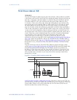
The pole discordance scheme in the 850-D relay allows two types of breaker contact
wiring:
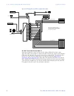
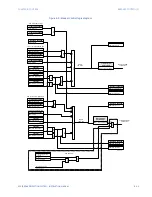
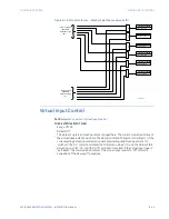
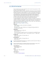
Figure 8-11:Detecting Pole Discordance externally
shows wiring of the breaker pole
discordance signal detected externally. In such schemes the three 52a contacts are
parallel and connected in series with the three parallel 52b contacts. If the External Pole
Discordance input turns ON, this indicates either one or more 52b contacts did not open
after a breaker close command, or one or more 52a contacts remained closed after a
breaker trip command.
Figure 8-11: Detecting Pole Discordance externally
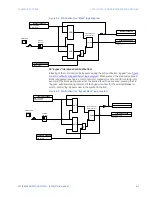
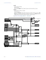
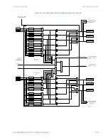
Figure 8-12:Pole Discordance detected by the relay
shows the connection of breaker 52a
and 52b auxiliary contacts per breaker pole, and their wiring to the relay inputs. This wiring
of the breaker contacts to the relay is used when the contact-based method for pole
discordance detection is enabled on the relay.
8xx relay
External Pole Discordance
Ia
Ib
Ic
Pole Discordance
52a
52a
52a
52b
52b
52b
Circuit Breaker
894180A1.cdr
Summary of Contents for Multilin 850
Page 10: ...VIII 850 FEEDER PROTECTION SYSTEM INSTRUCTION MANUAL ...
Page 135: ...CHAPTER 3 INTERFACES SOFTWARE INTERFACE 850 FEEDER PROTECTION SYSTEM INSTRUCTION MANUAL 3 41 ...
Page 151: ...CHAPTER 3 INTERFACES SOFTWARE INTERFACE 850 FEEDER PROTECTION SYSTEM INSTRUCTION MANUAL 3 57 ...
Page 153: ...CHAPTER 3 INTERFACES SOFTWARE INTERFACE 850 FEEDER PROTECTION SYSTEM INSTRUCTION MANUAL 3 59 ...
Page 439: ...CHAPTER 7 MONITORING FUNCTIONS 850 FEEDER PROTECTION SYSTEM INSTRUCTION MANUAL 7 19 ...
Page 644: ...11 20 850 FEEDER PROTECTION SYSTEM INSTRUCTION MANUAL FLEXELEMENTS CHAPTER 11 METERING ...