


4–2
850 FEEDER PROTECTION SYSTEM – INSTRUCTION MANUAL
SETPOINTS ENTRY METHODS
CHAPTER 4: ABOUT SETPOINTS
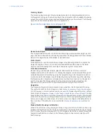
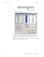
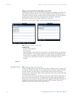
Figure 4-2: Main Setpoints Screen
Setpoints Entry Methods
Before placing the relay in operation, setpoints defining system characteristics, inputs,
relay outputs, and protection settings must be entered, using one of the following
methods:
•
Front panel, using the keypad and the display.
•
Front USB port, connected to a portable computer running the EnerVista 8 Series
Setup software.
•
Rear Ethernet (copper or fiber port connected to portable computer running the
EnerVista 8 Series Setup software.
•
Wi-Fi wireless connection to a portable computer running the EnerVista 8 Series Setup
software.
•
Rear RS485 port and a SCADA system running user-written software.
Any of these methods can be used to enter the same information. A computer, however,
makes entry much easier. Files can be stored and downloaded for fast, error free entry
when a computer is used. To facilitate this process, the GE EnerVista CD with the EnerVista
8 Series Setup software is supplied with the relay. The relay leaves the factory with
setpoints programmed to default values, and it is these values that are shown in all the
setpoint message illustrations.
At a minimum, the
Setpoints > System
setpoints must be entered for the system to function
correctly. To safeguard against the installation of a relay whose setpoints have not been
entered, the
Out-Of-Service
self-test warning is displayed. In addition, the Critical Failure
relay is de-energized. Once the relay has been programmed for the intended application,
the
Setpoints > Device > Installation > Device In Service
setpoint should be changed from
“Not Ready” (the default) to “Ready”.Before putting the relay in “Ready” state, each page of
setpoint messages should be worked through, entering values either by keypad or
computer.
Summary of Contents for Multilin 850
Page 10: ...VIII 850 FEEDER PROTECTION SYSTEM INSTRUCTION MANUAL ...
Page 135: ...CHAPTER 3 INTERFACES SOFTWARE INTERFACE 850 FEEDER PROTECTION SYSTEM INSTRUCTION MANUAL 3 41 ...
Page 151: ...CHAPTER 3 INTERFACES SOFTWARE INTERFACE 850 FEEDER PROTECTION SYSTEM INSTRUCTION MANUAL 3 57 ...
Page 153: ...CHAPTER 3 INTERFACES SOFTWARE INTERFACE 850 FEEDER PROTECTION SYSTEM INSTRUCTION MANUAL 3 59 ...
Page 439: ...CHAPTER 7 MONITORING FUNCTIONS 850 FEEDER PROTECTION SYSTEM INSTRUCTION MANUAL 7 19 ...
Page 644: ...11 20 850 FEEDER PROTECTION SYSTEM INSTRUCTION MANUAL FLEXELEMENTS CHAPTER 11 METERING ...