6–84
850 FEEDER PROTECTION SYSTEM – INSTRUCTION MANUAL
VOLTAGE ELEMENTS
CHAPTER 6: PROTECTION SETPOINTS
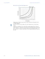
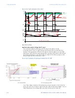
Figure 6-34: Inverse Time Undervoltage Curves
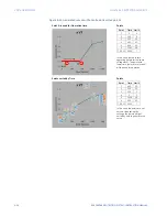
If FlexCurves are selected, the operating time determined based on following equation:
T= Flexcurve (V
pkp
/ V)
NOTE
NOTE:
FlexCurve reverses the ratio of voltages. The ratio of set pickup value to the measured
voltage.
Example: For a Pickup set to 0.9 x VT, when the measured voltage is 0.82 x VT, the ratio
would be 0.9/0.8 = 1.1, therefore in the FlexCurve, the corresponding Trip time setting entry
is at 1.1 x PKP (not at 0.82 x PKP). On the other hand, when the measured voltage is 1 x VT,
the ratio is 0.9/1 = 0.9, therefore, in the FlexCurve, the corresponding Reset time entry is at
0.9 x PKP.
Summary of Contents for Multilin 850
Page 10: ...VIII 850 FEEDER PROTECTION SYSTEM INSTRUCTION MANUAL ...
Page 135: ...CHAPTER 3 INTERFACES SOFTWARE INTERFACE 850 FEEDER PROTECTION SYSTEM INSTRUCTION MANUAL 3 41 ...
Page 151: ...CHAPTER 3 INTERFACES SOFTWARE INTERFACE 850 FEEDER PROTECTION SYSTEM INSTRUCTION MANUAL 3 57 ...
Page 153: ...CHAPTER 3 INTERFACES SOFTWARE INTERFACE 850 FEEDER PROTECTION SYSTEM INSTRUCTION MANUAL 3 59 ...
Page 439: ...CHAPTER 7 MONITORING FUNCTIONS 850 FEEDER PROTECTION SYSTEM INSTRUCTION MANUAL 7 19 ...
Page 644: ...11 20 850 FEEDER PROTECTION SYSTEM INSTRUCTION MANUAL FLEXELEMENTS CHAPTER 11 METERING ...


