CHAPTER 6: PROTECTION SETPOINTS
CURRENT ELEMENTS
850 FEEDER PROTECTION SYSTEM – INSTRUCTION MANUAL
6–3
Current Elements
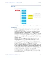
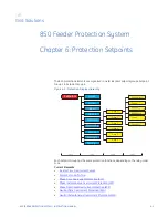
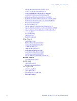
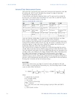
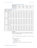
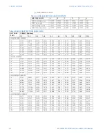
Figure 6-2: Current Elements Display Hierarchy
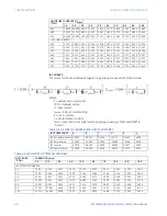
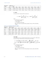
Description
The relay has six setpoint groups with several protection elements repeated in each group.
(Available protection elements depend on the 850 model: 850D, 850E, or 850P, and on the
exact relay order code.)The programming of the time-current characteristics of these
elements is identical in all cases and is only covered in this section. The required curve is
established by programming a Pickup Current, Curve Shape, Curve Multiplier, and Reset
Time. The Curve Shape can be either a standard shape or a user-defined shape
programmed with the FlexCurve feature. Accurate coordination may require changing the
time overcurrent characteristics of particular elements under different conditions. For
manual closing or picking up a cold load, a different time-current characteristic can be
produced by increasing the pickup current value. In the 850 relay, the pickup current can
be raised between autoreclose shots.
Setpoints
Device
System
Inputs
Outputs
Protection
Monitoring
Control
FlexLogic
Data Capture
Group 1
Phase TOC
Phase IOC
Phase Directional OC
Neutral IOC
Neutral Directional OC
Ground TOC
Ground IOC
Ground Directional OC
Negative Sequence TOC
Negative Sequence IOC
Negative Sequence Dir. OC
Broken Conductor
Load Encroachment
Thermal Overload
Neutral TOC
Level 1
Level 2
Level 3
Level 4
Restricted Ground Fault
Sensitive Ground TOC
Sensitive Ground IOC
Sens. Ground Directional OC
Level 5
Data Capture
Power
Frequency
Voltage
Current
Group 2
Group 3
Group 4
Group 5
Group 6
Testing
Feeder
Switch On To Fault
Undercurrent
Summary of Contents for Multilin 850
Page 10: ...VIII 850 FEEDER PROTECTION SYSTEM INSTRUCTION MANUAL ...
Page 135: ...CHAPTER 3 INTERFACES SOFTWARE INTERFACE 850 FEEDER PROTECTION SYSTEM INSTRUCTION MANUAL 3 41 ...
Page 151: ...CHAPTER 3 INTERFACES SOFTWARE INTERFACE 850 FEEDER PROTECTION SYSTEM INSTRUCTION MANUAL 3 57 ...
Page 153: ...CHAPTER 3 INTERFACES SOFTWARE INTERFACE 850 FEEDER PROTECTION SYSTEM INSTRUCTION MANUAL 3 59 ...
Page 439: ...CHAPTER 7 MONITORING FUNCTIONS 850 FEEDER PROTECTION SYSTEM INSTRUCTION MANUAL 7 19 ...
Page 644: ...11 20 850 FEEDER PROTECTION SYSTEM INSTRUCTION MANUAL FLEXELEMENTS CHAPTER 11 METERING ...

