8–100
850 FEEDER PROTECTION SYSTEM – INSTRUCTION MANUAL
CT SUPERVISION
CHAPTER 8: CONTROL
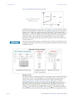
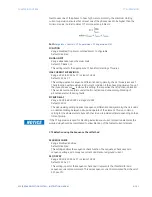
Figure 8-39: Differential Check characteristics
An additional setting
Setpoints > Monitoring > CT Supervision > Diff. IG
Polarity is provided
which allows changing the Core Balance CT polarity if the connections are reversed. The
setting can be changed after verifying the wiring of both Phase CTs and Core Balance CT. If
both Phase CT (I_0) and Core Balance CT (IG) are of the same polarity, the Diff. IG Polarity
setting can be set to “Same”. If the CT polarities are opposite, the Diff. IG Polarity setting
can be set to “Reverse”. The CTS Diff Current metering value can be used for further
verification. The figure below shows an example of ground CT connection and the Diff. IG
Polarity setting for it.
FASTPATH:
The CT Supervision element ground current input must come from a core balance CT. The
Transformer neutral point grounding or residual ground input method should not be used
for differential check.
Symmetry Check
The symmetry check continuously calculates the quotient Q between measured minimum
and maximum phase current magnitudes. Under normal balanced load conditions, this
value is close to unity. If the quotient falls below the set minimum permitted value
Setpoints > Monitoring > CT Supervision > Sym. Quotient PKP
(Q
min,perm
), it can be
concluded that there is a fault in one or more phase current paths of the CT. The pickup
should be set lower than the maximum allowed unbalance between the phases. An
additional check is added where the
I
max
must be greater than the minimum starting
current
I
Lmin
and lower than the maximum load current
I
Lmax
. This additional maximum
load current supervision ensures that the symmetry check does not operate when a real
Summary of Contents for Multilin 850
Page 10: ...VIII 850 FEEDER PROTECTION SYSTEM INSTRUCTION MANUAL ...
Page 135: ...CHAPTER 3 INTERFACES SOFTWARE INTERFACE 850 FEEDER PROTECTION SYSTEM INSTRUCTION MANUAL 3 41 ...
Page 151: ...CHAPTER 3 INTERFACES SOFTWARE INTERFACE 850 FEEDER PROTECTION SYSTEM INSTRUCTION MANUAL 3 57 ...
Page 153: ...CHAPTER 3 INTERFACES SOFTWARE INTERFACE 850 FEEDER PROTECTION SYSTEM INSTRUCTION MANUAL 3 59 ...
Page 439: ...CHAPTER 7 MONITORING FUNCTIONS 850 FEEDER PROTECTION SYSTEM INSTRUCTION MANUAL 7 19 ...
Page 644: ...11 20 850 FEEDER PROTECTION SYSTEM INSTRUCTION MANUAL FLEXELEMENTS CHAPTER 11 METERING ...

