


7–28
850 FEEDER PROTECTION SYSTEM – INSTRUCTION MANUAL
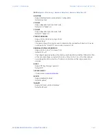
FUNCTIONS
CHAPTER 7: MONITORING
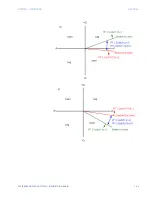
Reactive Power
The Reactive Power Demand is monitored by comparing to a Pickup value. If the Reactive
Power Demand Pickup is ever equalled or exceeded, the relay can be configured to cause
an alarm or signal an output relay.
Path
:
Setpoints > Monitoring > Functions > Demand > Reactive Power Demand 1(X)
FUNCTION
Range: Disabled, Alarm, Latched Alarm, Configurable
Default: Disabled
SIGNAL INPUT
Range: Power 1, Power 2, Power 3, Power 4, Dependant on order code
Default: Power 1
MEASUREMENT TYPE
Range: Blk Interval, Exponential, Rolling Dmd
Default: Blk Interval
The setting sets the measurement method. Three methods can be applied.
THERMAL 90% RESPONSE TIME
Range: 5 min, 10 min, 15 min, 20 min, 30 min
Default: 15 min
The setpoint sets the time required for a steady state Reactive Power to indicate 90% of
the actual value to approximately match the response of the relay to analog
instruments. The setpoint is visible only if MEASUREMENT TYPE is “Thermal Exponential”.
TIME INTERVAL
Range: 5 min, 10 min, 15 min, 20 min, 30 min
Default: 20 min
The setpoint sets the time period over which the Reactive Power Demand calculation is
to be performed. The setpoint is visible only if MEASUREMENT TYPE is “Block Interval” or
“Rolling Demand”.
PICKUP
Range: 0.1 to 300000.0 kvar in steps of 0.1 kvar.
Default: 1000.0 kvar
The setting sets the Reactive Power Demand Pickup level. The absolute value of reactive
power demand is used for the Pickup comparison.
BLOCK
Range: Off, Any FlexLogic operand
Default: Off
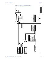
OUTPUT RELAY X
For details see
EVENTS
Range: Enabled, Disabled
Default: Enabled
TARGETS
Range: Disabled, Self-reset, Latched
Default: Self-reset
Summary of Contents for Multilin 850
Page 10: ...VIII 850 FEEDER PROTECTION SYSTEM INSTRUCTION MANUAL ...
Page 135: ...CHAPTER 3 INTERFACES SOFTWARE INTERFACE 850 FEEDER PROTECTION SYSTEM INSTRUCTION MANUAL 3 41 ...
Page 151: ...CHAPTER 3 INTERFACES SOFTWARE INTERFACE 850 FEEDER PROTECTION SYSTEM INSTRUCTION MANUAL 3 57 ...
Page 153: ...CHAPTER 3 INTERFACES SOFTWARE INTERFACE 850 FEEDER PROTECTION SYSTEM INSTRUCTION MANUAL 3 59 ...
Page 439: ...CHAPTER 7 MONITORING FUNCTIONS 850 FEEDER PROTECTION SYSTEM INSTRUCTION MANUAL 7 19 ...
Page 644: ...11 20 850 FEEDER PROTECTION SYSTEM INSTRUCTION MANUAL FLEXELEMENTS CHAPTER 11 METERING ...