


CHAPTER 8: CONTROL
BUS TRANSFER
850 FEEDER PROTECTION SYSTEM – INSTRUCTION MANUAL
8–75
It is imperative for Incomer 1 and Incomer 2 that the DEAD SOURCE PERMISSION setpoint
be “LL & DB” (Live Line and Dead Bus) to allow initial closing of the incoming breakers. The
user establishes all other setpoints for this element.
The Dead Source Permissive portion of the Bus Tie relay’s Synchrocheck function is also
used to measure the residual voltage on the bus that has lost source. To ensure that
Transfers are supervised by the decayed voltage magnitude only, the SYNC 1(2) DEAD
SOURCE PERMISSION is hardcoded for the Bus Tie relay. It is imperative that the DEAD
SOURCE PERMISSION setpoint for Bus Tie Relay be either “DL OR DB” (Dead Line or Dead
Bus) or “DL XOR DB” (Dead Line or Dead Bus, but not both) to allow for Transfers to either
Incomer.
The DEAD BUS VOLTS MAXIMUM and DEAD LINE VOLTS MAXIMUM setpoints establish the
level of decayed voltage above which Transfers are inhibited. A normal setting for this
element is about 0.25 of Pickup of nominal voltage. When the 850 measures a single
phase-phase voltage, these values should be multiplied by 1/
√
3 to cover the case of a
phase-ground fault on a measured phase reducing that phase voltage but leaving the
other two phases at a higher voltage. If experience shows this setpoint causes a delay of
transfer, presenting problems, it is occasionally raised to a maximum of 0.40 of Pickup. The
user establishes all other setpoints for this element.
If breaker status is taken from Breaker function, it is necessary to set all digital inputs for
that purpose.
The inputs needed for the Breaker Control function are required in order to define how the
relay receives external commands.
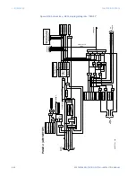
FASTPATH:
1.
The scheme design requires that the AC voltage connections for ‘Line’ and ‘Bus’
sources on the Incomer relays be in accordance with the Transfer Scheme One Line
Diagram shown above.
2.
The connection of AC voltage to the relay on the bus tie does not affect operation of
the scheme.
3.
The Output Relays used to send signals from one relay to the others (all breakers)
must not be operated by any other feature of the relay.
The Inputs for Incomers 1 and 2 and the Bus Tie relays that are programmed, must match
the wiring of the relays. It is necessary that the specific Inputs be programmed as per the
logic diagrams, and that field connections must match their specific functions within the
Transfer Scheme.
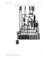
ATS Wiring Diagrams
The following diagrams show an example of three 850 relays used for Auto-transfer
scheme.
Summary of Contents for Multilin 850
Page 10: ...VIII 850 FEEDER PROTECTION SYSTEM INSTRUCTION MANUAL ...
Page 135: ...CHAPTER 3 INTERFACES SOFTWARE INTERFACE 850 FEEDER PROTECTION SYSTEM INSTRUCTION MANUAL 3 41 ...
Page 151: ...CHAPTER 3 INTERFACES SOFTWARE INTERFACE 850 FEEDER PROTECTION SYSTEM INSTRUCTION MANUAL 3 57 ...
Page 153: ...CHAPTER 3 INTERFACES SOFTWARE INTERFACE 850 FEEDER PROTECTION SYSTEM INSTRUCTION MANUAL 3 59 ...
Page 439: ...CHAPTER 7 MONITORING FUNCTIONS 850 FEEDER PROTECTION SYSTEM INSTRUCTION MANUAL 7 19 ...
Page 644: ...11 20 850 FEEDER PROTECTION SYSTEM INSTRUCTION MANUAL FLEXELEMENTS CHAPTER 11 METERING ...