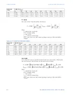
CHAPTER 6: PROTECTION SETPOINTS
CURRENT ELEMENTS
850 FEEDER PROTECTION SYSTEM – INSTRUCTION MANUAL
6–23
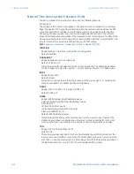
Neutral Instantaneous Overcurrent Protection (50N)
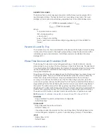
The 850 Neutral Instantaneous Overcurrent protection element computes the neutral
current (In) using the following formula:
|In| = |Ia + Ib + Ic|
The element essentially responds to the magnitude of a neutral current fundamental
frequency phasor calculated from the phase currents. A positive-sequence restraint is
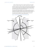
applied for better performance. A small portion (6.25%) of the positive-sequence current
magnitude is subtracted from the zero-sequence current magnitude when forming the
operating quantity of the element as follows:
Iop = 3 * (|I_0| - K * |I_1|)
where K = 1/16 and |I_0| = 1/3 * |In|
The positive-sequence restraint allows for more sensitive settings by counterbalancing
spurious zero-sequence currents resulting from:
•
system unbalances under heavy load conditions
•
current transformer (CT) transformation errors of during double-line and three-phase
faults
•
switch-off transients during double-line and three-phase faults
The positive-sequence restraint must be considered when testing for Pickup accuracy and
response time (multiple of Pickup). The operating quantity depends on how test currents
are injected into the relay (single-phase injection: Iop = 0.9375 * I_injected three-phase
pure zero sequence injection: Iop = 3 * I_injected).
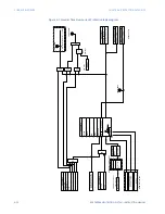
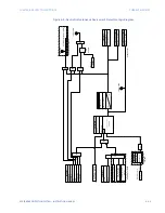
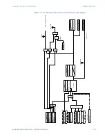
The settings of this function are applied to the neutral current to produce Pickup and Trip
flags. The Neutral IOC Pickup flag is asserted, when the neutral current is above the PKP
value. The Neutral IOC Operate flag is asserted if the element stays picked up for the time
defined by the Neutral IOC PKP Delay setting. If the Pickup time delay is set to 0.000
seconds, the Pickup and Operate flags are asserted at the same time. The element drops
from Pickup without operation if the neutral current drops below 97 to 98% of the Pickup
value.
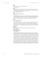
Path
:
Setpoints > Protection > Group 1(6) > Current > Neutral IOC 1(X)
FUNCTION
Range: Disabled, Trip, Alarm, Latched Alarm, Configurable
Default: Disabled
SIGNAL INPUT
Range: dependant upon the order code
Default: CT Bank 1-J1
This setting provides the selection for the current input bank. The default bank names
can be changed in: Setpoints > System > Current Sensing > [Name] > CT Bank Name.
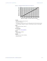
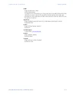
PICKUP
Range: 0.050 to 30.000 x CT in steps of 0.001 x CT
Default: 1.000 x CT
DIRECTION
Range: Disabled, Forward (Ntrl Dir OC [1-4] FWD), Reverse (Ntrl Dir OC [1-4] REV)
Default: Disabled
PICKUP DELAY
Range: 0.000 to 6000.000 s in steps of 0.001 s
Default: 0.000 s
DROPOUT DELAY
Range: 0.000 to 6000.000 s in steps of 0.001 s
Default: 0.000 s
Summary of Contents for Multilin 850
Page 10: ...VIII 850 FEEDER PROTECTION SYSTEM INSTRUCTION MANUAL ...
Page 135: ...CHAPTER 3 INTERFACES SOFTWARE INTERFACE 850 FEEDER PROTECTION SYSTEM INSTRUCTION MANUAL 3 41 ...
Page 151: ...CHAPTER 3 INTERFACES SOFTWARE INTERFACE 850 FEEDER PROTECTION SYSTEM INSTRUCTION MANUAL 3 57 ...
Page 153: ...CHAPTER 3 INTERFACES SOFTWARE INTERFACE 850 FEEDER PROTECTION SYSTEM INSTRUCTION MANUAL 3 59 ...
Page 439: ...CHAPTER 7 MONITORING FUNCTIONS 850 FEEDER PROTECTION SYSTEM INSTRUCTION MANUAL 7 19 ...
Page 644: ...11 20 850 FEEDER PROTECTION SYSTEM INSTRUCTION MANUAL FLEXELEMENTS CHAPTER 11 METERING ...


