CHAPTER 5: DEVICE, SYSTEM, INPUT AND OUTPUT SETPOINTS
DEVICE
850 FEEDER PROTECTION SYSTEM – INSTRUCTION MANUAL
5–41
configured channels at the instance of the rising edge of the trigger (FlexLogic operand).
The data logger ignores all subsequent triggers and continues to record data until the
active record is full. Once the data logger is full, capturing of data stops until it is cleared.
Clear Data Logger
Once the data logger is full, a Clear Data Logger command is required to clear the data
logger record, before a new record can be started. Performing the Clear Data Logger
command also stops the current record and resets the data logger to be ready for the
next trigger. The Clear Data Logger command is located at
Setpoints > Records > Clear
Records
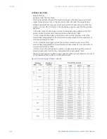
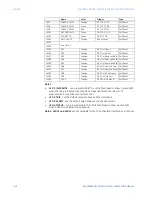
. The Data Logger Storage Capacity table below shows an example of the
dependency of the data logger storage capacity with respect to the selected number of
channels, and the selected rate (time interval) at which the logged values are taken. The
Data Logger buffer space can be monitored to produce an alarm when the logged data
occupies 80% of the data logger storage space. Target message, and operand “Data
Logger ALRM” is generated at this time.
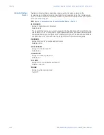
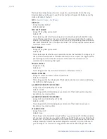
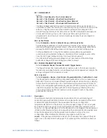
TRIGGER
Range: Off, Any FlexLogic operand
Default: Off
This setting selects the signal used to trigger the start of a new data logger record. Any
FlexLogic operand can be used as a trigger source. The Triggered setting only applies
when the Data Logger Function is set to “Triggered”.
TRIGGER POSITION
Range: 0 to 50% steps of 1%
Default: 20%
This setpoint defines the percentage of buffer space that is used for recording pre-
trigger samples.
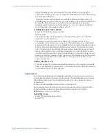
RATE
Range: 1 cycle, 1 second, 30 seconds, 1 minute, 15 minutes, 30 minutes, 1 hour
Default: 1 minute
This setting selects the time interval at which the actual value is recorded.
CHANNEL 1(16) SOURCE
Range: Off, Any FlexAnalog parameter
Default: Off
This setpoint selects the metering analog value that is to be recorded in Channel 1(16) of
the data log. The parameters available in a given relay are dependent on: the type of
relay, the type and number of CT/VT hardware installed, and the type and number of
Analog Inputs hardware installed. Upon startup, the relay automatically prepares the
parameter list.
Summary of Contents for Multilin 850
Page 10: ...VIII 850 FEEDER PROTECTION SYSTEM INSTRUCTION MANUAL ...
Page 135: ...CHAPTER 3 INTERFACES SOFTWARE INTERFACE 850 FEEDER PROTECTION SYSTEM INSTRUCTION MANUAL 3 41 ...
Page 151: ...CHAPTER 3 INTERFACES SOFTWARE INTERFACE 850 FEEDER PROTECTION SYSTEM INSTRUCTION MANUAL 3 57 ...
Page 153: ...CHAPTER 3 INTERFACES SOFTWARE INTERFACE 850 FEEDER PROTECTION SYSTEM INSTRUCTION MANUAL 3 59 ...
Page 439: ...CHAPTER 7 MONITORING FUNCTIONS 850 FEEDER PROTECTION SYSTEM INSTRUCTION MANUAL 7 19 ...
Page 644: ...11 20 850 FEEDER PROTECTION SYSTEM INSTRUCTION MANUAL FLEXELEMENTS CHAPTER 11 METERING ...

