
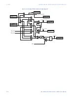
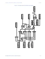


CHAPTER 5: DEVICE, SYSTEM, INPUT AND OUTPUT SETPOINTS
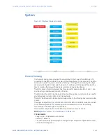
SYSTEM
850 FEEDER PROTECTION SYSTEM – INSTRUCTION MANUAL
5–77
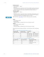
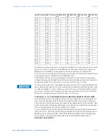
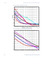
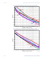
The first two columns (40 points) correspond to the RESET curve. The other 4 columns, with
80 points in total, correspond to the OPERATE curve. The reset characteristic values are
between 0 and 0.98xPKP, and the operation values are between 1.03 and 20xPKP.
The final curve is created by means of a linear interpolation from the defined points. This is
a separate process for the RESET and the OPERATE curve.
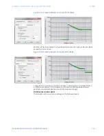
The definition of these points is performed in a separate module from the relay, using a
configuration program included in EnerVista 8 Series Setup software, which incorporates a
graphical environment for viewing the curve, thus making it easy to create.
FASTPATH:
The relay using a given FlexCurve applies linear approximation for times lying between the
user-entered points. Special care must be taken when setting the two points that are close
to a Pickup multiple of 1; that is, 0.98*I
pickup
and 1.03*I
pickup
. It is recommended to set the
two times to a similar value, otherwise, the linear approximation may result in undesired
behavior for the operating quantity that is close to 1.00*I
pickup
.
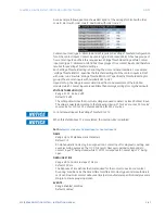
FLEXCURVE A, B, C, D CONFIGURATION WITH ENERVISTA 8 SERIES SETUP SOFTWARE
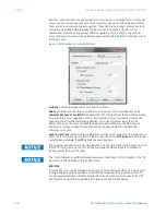
The EnerVista 8 Series Setup software allows for easy configuration and management of
FlexCurves and their associated data points. Prospective FlexCurves can be configured
from a selection of standard curves to provide the best approximate fit, then specific data
points can be edited afterwards. Alternately, curve data can be imported from a specified
file (.csv format) by selecting the Import Data From setting.
Curves and data can be exported, viewed, and cleared by clicking the appropriate buttons.
FlexCurves A, B, C, and D are customized by editing the operating time (ms) values at pre-
defined per-unit current multiples. Note that the pickup multiples start at zero (implying
the "reset time"), operating time below Pickup, and operating time above Pickup.
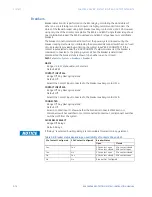
RECLOSER CURVE EDITING
RESET TIME ms RESET TIME ms OPERATE TIME
ms
OPERATE TIME
ms
OPERATE TIME
ms
OPERATE TIME
ms
0.00
0.68
1.03
2.9
4.9
10.5
0.05
0.70
1.05
3.0
5.0
11.0
0.10
0.72
1.1
3.1
5.1
11.5
0.15
0.74
1.2
3.2
5.2
12.0
0.20
0.76
1.3
3.3
5.3
12.5
0.25
0.78
1.4
3.4
5.4
13.0
0.30
0.80
1.5
3.5
5.5
13.5
0.35
0.82
1.6
3.6
5.6
14.0
0.40
0.84
1.7
3.7
5.7
14.5
0.45
0.86
1.8
3.8
5.8
15.0
0.48
0.88
1.9
3.9
5.9
15.5
0.50
0.90
2.0
4.0
6.0
16.0
0.52
0.91
2.1
4.1
6.5
16.5
0.54
0.92
2.2
4.2
7.0
17.0
0.56
0.93
2.3
4.3
7.5
17.5
0.58
0.94
2.4
4.4
8.0
18.0
0.60
0.95
2.5
4.5
8.5
18.5
0.62
0.96
2.6
4.6
9.0
19.0
0.64
0.97
2.7
4.7
9.5
19.5
0.66
0.98
2.8
4.8
10.0
20.0
Summary of Contents for Multilin 850
Page 10: ...VIII 850 FEEDER PROTECTION SYSTEM INSTRUCTION MANUAL ...
Page 135: ...CHAPTER 3 INTERFACES SOFTWARE INTERFACE 850 FEEDER PROTECTION SYSTEM INSTRUCTION MANUAL 3 41 ...
Page 151: ...CHAPTER 3 INTERFACES SOFTWARE INTERFACE 850 FEEDER PROTECTION SYSTEM INSTRUCTION MANUAL 3 57 ...
Page 153: ...CHAPTER 3 INTERFACES SOFTWARE INTERFACE 850 FEEDER PROTECTION SYSTEM INSTRUCTION MANUAL 3 59 ...
Page 439: ...CHAPTER 7 MONITORING FUNCTIONS 850 FEEDER PROTECTION SYSTEM INSTRUCTION MANUAL 7 19 ...
Page 644: ...11 20 850 FEEDER PROTECTION SYSTEM INSTRUCTION MANUAL FLEXELEMENTS CHAPTER 11 METERING ...