


CHAPTER 5: DEVICE, SYSTEM, INPUT AND OUTPUT SETPOINTS
DEVICE
850 FEEDER PROTECTION SYSTEM – INSTRUCTION MANUAL
5–45
setting of
Voltage Sensing
. In addition, the relay will check if the auxiliary signal
configured is marked as
Vn
(under VT setup), and inhibit the fault location if the auxiliary
signal is labeled differently.
If the broken-delta neutral voltage is not available to the relay, an approximation is
possible by assuming the missing zero sequence voltage to be an inverted voltage drop
produced by the zero-sequence current and the user-specified equivalent zero-
sequence system impedance behind the relay: V0 = –Z0 × I0. In order to enable this
mode of operation, this setting should be set to “I0”.
Z_0 (RESISTIVE/INDUCTIVE) OF SYSTEM
Range: 0.01 to 99.99
Ω
in steps of 0.01
Ω
Default: 0.01
Ω
This setting sets the total real/imaginary component of the system zero sequence
impedance, in secondary ohms.
The settings are used only when the VT SUBSTITUTION setting value is “I0”. The
magnitude is to be entered in secondary ohms. This impedance is an average system
equivalent behind the relay. It can be calculated as zero-sequence Thevenin impedance
at the local bus with the protected line/feeder disconnected. The method is accurate
only if this setting matches perfectly the actual system impedance during the fault. If
the system exhibits too much variability, this approach is questionable and the fault
location results for single-line-to-ground faults should be trusted accordingly. It should
be kept in mind that grounding points in the vicinity of the installation impact the system
zero-sequence impedance (grounded loads, reactors, zig-zag transformers, shunt
capacitor banks, etc.).
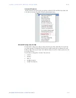
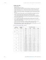
ANALOG CHANNELS 1 to 32
These settings specify an actual value such as voltage or current magnitude, true RMS,
phase angle, frequency, temperature, etc., to be stored should the report be created. Up
to 32 analog channels can be configured.
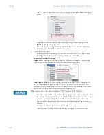
Event Data
The Event Data feature stores 64 FlexAnalog quantities each time an event occurs. The
relay is able to capture a maximum of 1024 records. The Event Data behaviour matches
that of the Event Recorder. This is a Platform feature and a ‘Basic’ option so it has no
dependencies.
There is no Enabling/Disabling of the feature. It is always ‘ON’.
When changes are made to the Event Data settings, the Event data is cleared and the
Snapshot.txt file is deleted. The Event Record remains as is and is not cleared.
Path
:
Setpoints > Device > Event Data
PARAMETER 1 to 64
Range: Off, any FlexAnalog Parameter
Default: Off
Summary of Contents for Multilin 850
Page 10: ...VIII 850 FEEDER PROTECTION SYSTEM INSTRUCTION MANUAL ...
Page 135: ...CHAPTER 3 INTERFACES SOFTWARE INTERFACE 850 FEEDER PROTECTION SYSTEM INSTRUCTION MANUAL 3 41 ...
Page 151: ...CHAPTER 3 INTERFACES SOFTWARE INTERFACE 850 FEEDER PROTECTION SYSTEM INSTRUCTION MANUAL 3 57 ...
Page 153: ...CHAPTER 3 INTERFACES SOFTWARE INTERFACE 850 FEEDER PROTECTION SYSTEM INSTRUCTION MANUAL 3 59 ...
Page 439: ...CHAPTER 7 MONITORING FUNCTIONS 850 FEEDER PROTECTION SYSTEM INSTRUCTION MANUAL 7 19 ...
Page 644: ...11 20 850 FEEDER PROTECTION SYSTEM INSTRUCTION MANUAL FLEXELEMENTS CHAPTER 11 METERING ...