CHAPTER 6: PROTECTION SETPOINTS
CURRENT ELEMENTS
850 FEEDER PROTECTION SYSTEM – INSTRUCTION MANUAL
6–29
POS SEQ RESTRAINT
Range: 0.000 to 0.500 in steps of 0.001
Default: 0.063
This setting controls the amount of the positive-sequence restraint. Set to zero to
remove the restraint. Set higher if large system unbalances or poor CT performance are
expected.
FORWARD ECA
Range: –90° to 90° in steps of 1°
Default: 75°
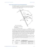
This setting defines the element characteristic angle (ECA) for the forward direction in
"Voltage" polarizing mode. "Current" polarizing mode uses a fixed ECA of 0°. The ECA in
the reverse direction is the angle set for the forward direction shifted by 180°.
FORWARD LIMIT ANGLE
Range: 40° to 90° in steps of 1°
Default: 90°
This setting defines a symmetrical (in both directions from the ECA) limit angle for the
forward direction.
FORWARD PICKUP
Range: 0.050 to 30.000 x CT in steps of 0.001 x CT
Default: 0.050 x CT
This setting defines the Pickup level for the overcurrent unit of the element in the
forward direction. When selecting this setting it must be kept in mind that the design
uses a ‘positive-sequence restraint’ technique for the “Calculated 3I0” mode of
operation.
REVERSE LIMIT ANGLE
Range: 40° to 90° in steps of 1°
Default: 90°
This setting defines a symmetrical (in both directions from the ECA) limit angle for the
reverse direction.
REVERSE PICKUP
Range: 0.050 to 30.000 x CT in steps of 0.001 x CT
Default: 0.050 x CT
This setting defines the Pickup level for the overcurrent unit of the element in the reverse
direction. When selecting this setting it must be kept in mind that the design uses a
‘positive-sequence restraint’ technique for the “Calculated 3I0” mode of operation.
BLOCK
Range: Off, Any FlexLogic operand
Default: Off
EVENTS
Range: Enabled, Disabled
Default: Enabled
TARGETS
Range: Self-reset, Latched, Disabled
Default: Self-reset
Summary of Contents for Multilin 850
Page 10: ...VIII 850 FEEDER PROTECTION SYSTEM INSTRUCTION MANUAL ...
Page 135: ...CHAPTER 3 INTERFACES SOFTWARE INTERFACE 850 FEEDER PROTECTION SYSTEM INSTRUCTION MANUAL 3 41 ...
Page 151: ...CHAPTER 3 INTERFACES SOFTWARE INTERFACE 850 FEEDER PROTECTION SYSTEM INSTRUCTION MANUAL 3 57 ...
Page 153: ...CHAPTER 3 INTERFACES SOFTWARE INTERFACE 850 FEEDER PROTECTION SYSTEM INSTRUCTION MANUAL 3 59 ...
Page 439: ...CHAPTER 7 MONITORING FUNCTIONS 850 FEEDER PROTECTION SYSTEM INSTRUCTION MANUAL 7 19 ...
Page 644: ...11 20 850 FEEDER PROTECTION SYSTEM INSTRUCTION MANUAL FLEXELEMENTS CHAPTER 11 METERING ...

