


CHAPTER 4 PARAMETER
Automatic Operation Setting Parameters
4-67
4
Non-overflow: Repetitive rotation in the same direction can be made.
The position is preset at the start, and all position data is handled as an incremental
value. The OT function, software OT and hardware OT functions allocated to input
signals are disabled.
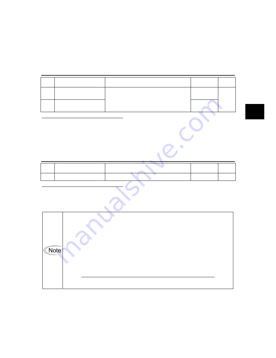
PA2_28 and 29 Limiter detection position
No. Name
Setting
range
Default value
Change
28
Positive Iimiter detection
position
2000000000
29
Negative Iimiter detection
position
-2000000000 to 2000000000 [unit amount]
-2000000000
Always
This parameter is enabled only for LS type.
Enter the position of the limiter detection function.
While each setting can be positive or negative, the setting of PA2_28 must not be smaller than the
setting of PA2_29.
For detail description of limiter detection, refer to “CHAPTER 2
WIRING.”
PA2_30 Backlash compensation
No. Name
Setting
range
Default value
Change
30 Backlash compensation 0 to 200000 [pulse]
0
Always
This parameter is enabled only for LS type.
Backlash in mechanical system can be compensated using the servomotor rotation amount.
The servomotor rotates with adding the amount of set value each time the servomotor changes the
direction of rotation.
When using this function, make sure to adjust followings. If it is not observed, the
operation may fail.
(1) Before setting a value to this parameter, adjust acceleration/deceleration time
(PA1_37 to 40) and low-pass filter (for S-curve) time constant (PA1_52) for the servo
amplifier to prevent the travel of mechanical system from inertia or similar despite the
motor stoppage while all operations (positioning, manual feed, homing, and pulse
operation) are stopped.
・
With the mechanical structure as shown on the next page, adjust the motor to stop
in the state as instructed in the figure.
(2) Next, set the backlash value to this parameter. The set value is a motor encoder pulse
or equivalent. In the case of the reference figure on the next page, the set value is
determined as follows.
Backlash compensation value = 262144 [pulse] ×(
θ
/360°) : at 18 bit PG
(3) After the setting, check if the positioning is carried out without influence of backlash by
performing normal operation.
Summary of Contents for ALPHA 5 RYT-SX
Page 1: ...MEHT301a FUJI SERVO SYSTEM USER S MANUAL RYT SX type ...
Page 19: ...0 1 CHAPTER 0 INTRODUCTION 0 ...
Page 34: ...CHAPTER 0 INTRODUCTION 0 16 Combination between Servomotor and Servo Amplifier 0 ...
Page 35: ...1 1 CHAPTER 1 INSTALLATION 1 ...
Page 45: ...2 1 CHAPTER 2 WIRING 2 ...
Page 142: ...CHAPTER 2 WIRING 2 98 Description of I O Signals 2 ...
Page 143: ...3 1 CHAPTER 3 OPERATION 3 ...
Page 197: ...4 1 CHAPTER 4 PARAMETER 4 ...
Page 296: ...CHAPTER 4 PARAMETER 4 100 Output Terminal Function Setting Parameters 4 ...
Page 297: ...5 1 CHAPTER 5 SERVO ADJUSTMENT 5 ...
Page 329: ...6 1 CHAPTER 6 KEYPAD 6 ...
Page 371: ...7 1 CHAPTER 7 MAINTENANCE AND INSPECTION 7 ...
Page 389: ...8 1 CHAPTER 8 SPECIFICATIONS 8 ...
Page 414: ...CHAPTER 8 SPECIFICATIONS 8 26 Dimensions of Servo Amplifier 8 ...
Page 415: ...9 1 CHAPTER 9 CHARACTERISTICS 9 ...
Page 425: ...10 1 CHAPTER 10 PERIPHERAL EQUIPMENT 10 ...
Page 463: ...11 1 CHAPTER 11 ABSOLUTE POSITION SYSTEM 11 ...
Page 473: ...12 1 CHAPTER 12 POSITIONING DATA 12 ...
Page 482: ...CHAPTER 12 POSITIONING DATA 12 10 Response Time 12 ...
Page 483: ...13 1 CHAPTER 13 PC LOADER 13 ...
Page 513: ...14 1 CHAPTER 14 APPENDIXES 14 ...
Page 545: ...CHAPTER 14 APPENDIXES Service Network 14 33 14 14 8 Service Network ...
Page 546: ...CHAPTER 14 APPENDIXES 14 34 Service Network 14 ...


