


CHAPTER 4 PARAMETER
Automatic Operation Setting Parameters
4-59
4
(6) Homing profile without using OT
Below is an example of the setting for returning to the home position with the home position LS
signal without the OT signal. Use this profile for mechanical configurations where one of directions
of the moving part of the mechanical system is turned on with the home position LS signal as
shown in the figure below. The starting direction for homing is automatically determined according
to the setting of PA2_10 (homing direction after reference signal detection) and the ON/OFF state
of the home position LS at which return begins.
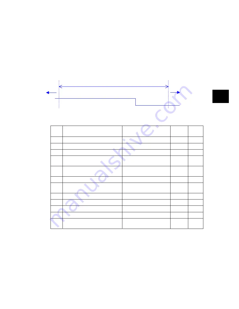
[An example of relationship between moving range of machine and home position LS]
Moving range of machine
Reverse
rotation
Forward
rotation
LS
OFF
ON
[Parameter setting example]
PA2_
No. Name
Setting
Default
value
Change
06
Homing speed
500.00 [r/min]
500.00
Always
07
Creep speed for homing
50.00 [r/min]
50.00
Always
08
Starting direction for homing
2: Condition judgment start
0
Power
09
Reverse traveling unit amount for
homing
0 [unit amount]
0
Always
10
Homing direction after reference signal
detection
0: Forward rotation
0 Power
11
Reference signal for shift operation
1: Z-phase of encoder
1
Power
12
Reference signal for homing
(Deceleration starting signal)
0: Home position LS
0 Power
13
Home position LS signal edge selection 0: Rising edge timing
0
Power
14
Home position shift unit amount
1000 [unit amount]
1000
Always
15
Deceleration operation for creep speed 1: Reverse rotation
is enabled
0 Power
16
Home position after homing completion 0 [unit amount]
0
Always
17
Home position detection range
0: Always ON after homing
completion
0 Always
•
PA2_13: Home position LS signal edge selection indicates selection of the edge of the home
position LS corresponding to the direction of homing.
If PA2_08 is set at “2,” use of the home position LS is assumed. Accordingly the following
conditions are included in combination conditions.
PA2_11 (Reference signal for shift operation) = 0 (home position LS) or
PA2_11 (Reference signal for shift operation) = 1 (encoder Z-phase) and PA2_12 (reference signal for
homing) = 0 (home position LS)
Summary of Contents for ALPHA 5 RYT-SX
Page 1: ...MEHT301a FUJI SERVO SYSTEM USER S MANUAL RYT SX type ...
Page 19: ...0 1 CHAPTER 0 INTRODUCTION 0 ...
Page 34: ...CHAPTER 0 INTRODUCTION 0 16 Combination between Servomotor and Servo Amplifier 0 ...
Page 35: ...1 1 CHAPTER 1 INSTALLATION 1 ...
Page 45: ...2 1 CHAPTER 2 WIRING 2 ...
Page 142: ...CHAPTER 2 WIRING 2 98 Description of I O Signals 2 ...
Page 143: ...3 1 CHAPTER 3 OPERATION 3 ...
Page 197: ...4 1 CHAPTER 4 PARAMETER 4 ...
Page 296: ...CHAPTER 4 PARAMETER 4 100 Output Terminal Function Setting Parameters 4 ...
Page 297: ...5 1 CHAPTER 5 SERVO ADJUSTMENT 5 ...
Page 329: ...6 1 CHAPTER 6 KEYPAD 6 ...
Page 371: ...7 1 CHAPTER 7 MAINTENANCE AND INSPECTION 7 ...
Page 389: ...8 1 CHAPTER 8 SPECIFICATIONS 8 ...
Page 414: ...CHAPTER 8 SPECIFICATIONS 8 26 Dimensions of Servo Amplifier 8 ...
Page 415: ...9 1 CHAPTER 9 CHARACTERISTICS 9 ...
Page 425: ...10 1 CHAPTER 10 PERIPHERAL EQUIPMENT 10 ...
Page 463: ...11 1 CHAPTER 11 ABSOLUTE POSITION SYSTEM 11 ...
Page 473: ...12 1 CHAPTER 12 POSITIONING DATA 12 ...
Page 482: ...CHAPTER 12 POSITIONING DATA 12 10 Response Time 12 ...
Page 483: ...13 1 CHAPTER 13 PC LOADER 13 ...
Page 513: ...14 1 CHAPTER 14 APPENDIXES 14 ...
Page 545: ...CHAPTER 14 APPENDIXES Service Network 14 33 14 14 8 Service Network ...
Page 546: ...CHAPTER 14 APPENDIXES 14 34 Service Network 14 ...


