


6.4 Setting Group No. for Centralized Control
45
Fundamental of DIII-NET
6.4.4 HRV Wired Remote Controller <BRC301B61>
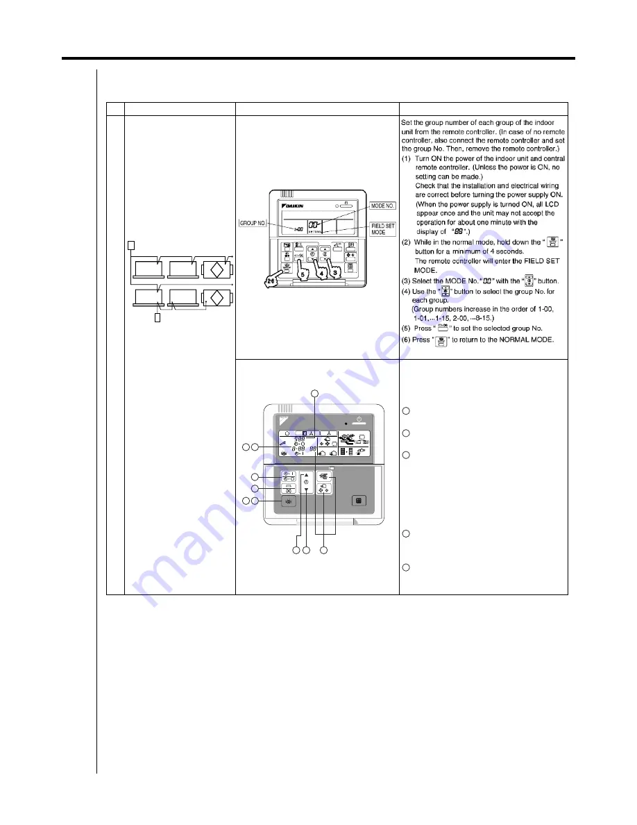
The following shows the procedure how to set the group number for the centralized controller by the remote controller for indoor unit.
Purpose
When you use the central
remote controller and the
unified ON / OFF controller, you
have to set the each unit
connected to the central
transmission line.
<Example>
Controller
z
Remote controller for indoor unit BRC1C62
z
BRC301B61
Operating procedure
The unit in [ ] does not require the group no.
setting for the centralized controller
connected to the central transmission line.
(Auto-address setting)
Press the INSPECTION button for more than
four seconds.
Use the VENTILATION MODE, AIR FLOW
RATE to select the mode no. “00”.
Use the top or lower section of the TIMER
button to set the group no. for the centralized
controller.
(When you use the unified ON / OFF
controller, it displays only the group no.
selected by the setting switch for zone
control.)
Press the PROGRAM / CANCEL button to
enter the setting group no. shown on the
display.
Press INSPECTION button to return to normal
mode.
Note:
Do not duplicate the group number.
Be sure to supply the power to the remote controller side.
(It cannot be set without the power supply.)
Central remote controller
or
ON / OFF controller
No necessary
Remote controller
for indoor unit
BRC301B61
H RV
UNIT No.
FRESH UP
CODE
GROUP
A
A
hr
hr
SETTING
[1-00]
[1-01]
[1-03]
[1-02]
1
4
3
2
5
1 7
4
3
3
2
5
4 5
6
Summary of Contents for D-BACS
Page 1: ...ED 72 721 Preliminary Daikin Buildings Air conditioning Control System D BACS DESIGN GUIDE ...
Page 17: ...xvi 1 5 Open Network Glossary Introduction ...
Page 41: ...24 Outline of D BACS System ...
Page 74: ...57 Remote Controllers HRV Wired remote controller BRC301B61 VAM ...
Page 107: ...90 5 4 HRV BRC301B61 Remote Controllers ...
Page 142: ...1 2 System Configuration 125 Control Devices 1 2 System Configuration System Outline ...
Page 181: ...164 3 8 Error Diagnosing Function Control Devices ...
Page 215: ...198 3 8 Wiring Example intelligent Manager ...
Page 235: ...218 Interface for Use in BACnet ...
Page 253: ...236 Interface for use in LONWORKS 10 Reference Materials Error Code Conversion Table ...
Page 268: ...251 Interface for use in LONWORKS 13 Workflow ...
Page 285: ...268 1 6 Notes Power Proportional Distribution P P D ...