5
Click Home tab
➤
View panel
➤
views drop-down
➤
Extents.
The drawing window zooms to the extents of the surface. With the
breakline data added, the layer that contained the source data for the
breaklines can be frozen.
6
Click Home tab
➤
Layers panel
➤
Layer drop-down. Next to the
EG_BREAKLINES
layer, click
.
Further exploration:
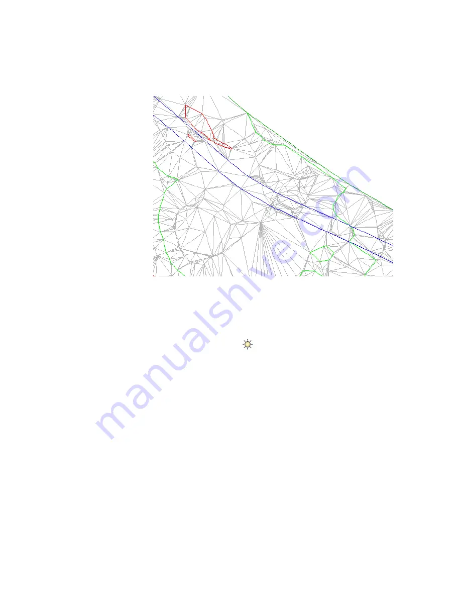
Notice that, along some portions of the polylines, the
surface triangulation incorrectly crosses the breakline. This happened because
the surface contours also act as breaklines. The new breaklines are not added
because the contours are already acting as breaklines, and the current surface
setting does not allow more than one breakline to affect the surface at a given
point. To override this behavior, you can perform any of the following tasks:
■
Build the surface with contours and breaklines:
In the Surface Properties
dialog box, on the Definition tab, expand the Build collection. Set Allow
Crossing Breaklines to Yes, and then set Elevation to Use to Use Last
Breakline Elevation at Intersection.
Exercise 3: Adding Breaklines to a Surface | 69
Summary of Contents for AUTOCAD PLANT 3D 2011 - SYSTEM REQUIREMENTS
Page 1: ...AutoCAD Civil 3D 2011 Tutorials April 2010 ...
Page 58: ...46 ...
Page 70: ...58 ...
Page 73: ...Tutorial Creating and Adding Data to a Surface 61 ...
Page 140: ...128 ...
Page 378: ...7 Press Enter 366 Chapter 10 Parcels Tutorials ...
Page 385: ...8 Press Enter Exercise 2 Swinging One End of a Parcel Lot Line 373 ...
Page 432: ...420 ...
Page 470: ...458 ...
Page 506: ...494 Chapter 13 Corridors Tutorials ...
Page 580: ...568 ...
Page 668: ...656 ...
Page 678: ...23 Change your view to SW isometric 666 Chapter 18 Part Builder Tutorials ...
Page 679: ...24 Change your visual style to Conceptual Exercise 2 Defining the Manhole Geometry 667 ...
Page 706: ...694 Chapter 18 Part Builder Tutorials ...
Page 830: ...818 ...
Page 832: ...tutorial folder AutoCAD Civil 3D installation location Help Civil Tutorials 820 Glossary ...


