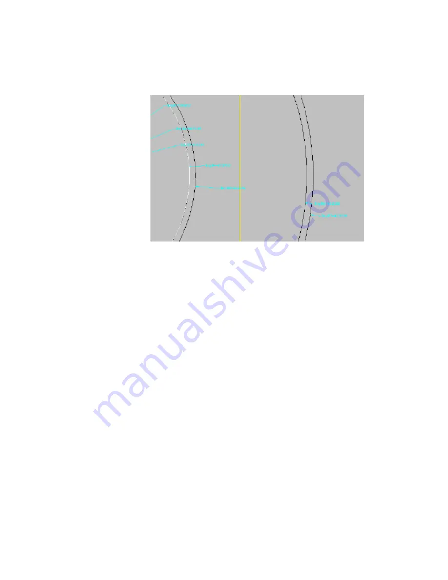
21
Change your view to a Front view. The stack of work planes and the
transitions created in step 17 are displayed.
22
Following the same methodology for the first batch of transitions created
in steps 16 and 17, add transitions between the Top of Riser 2 Profile,
and the smaller Top of Barrel profile, then the larger Top of Barrel profile
and the Bottom of Structure profile. (You may have to use Draw Order
to send certain profiles to the back, in order to choose the correct one
for each transition.) The model you created should now look similar to
the following illustration:
Exercise 2: Defining the Manhole Geometry | 665
Summary of Contents for AUTOCAD PLANT 3D 2011 - SYSTEM REQUIREMENTS
Page 1: ...AutoCAD Civil 3D 2011 Tutorials April 2010 ...
Page 58: ...46 ...
Page 70: ...58 ...
Page 73: ...Tutorial Creating and Adding Data to a Surface 61 ...
Page 140: ...128 ...
Page 378: ...7 Press Enter 366 Chapter 10 Parcels Tutorials ...
Page 385: ...8 Press Enter Exercise 2 Swinging One End of a Parcel Lot Line 373 ...
Page 432: ...420 ...
Page 470: ...458 ...
Page 506: ...494 Chapter 13 Corridors Tutorials ...
Page 580: ...568 ...
Page 668: ...656 ...
Page 678: ...23 Change your view to SW isometric 666 Chapter 18 Part Builder Tutorials ...
Page 679: ...24 Change your visual style to Conceptual Exercise 2 Defining the Manhole Geometry 667 ...
Page 706: ...694 Chapter 18 Part Builder Tutorials ...
Page 830: ...818 ...
Page 832: ...tutorial folder AutoCAD Civil 3D installation location Help Civil Tutorials 820 Glossary ...


