NOTE
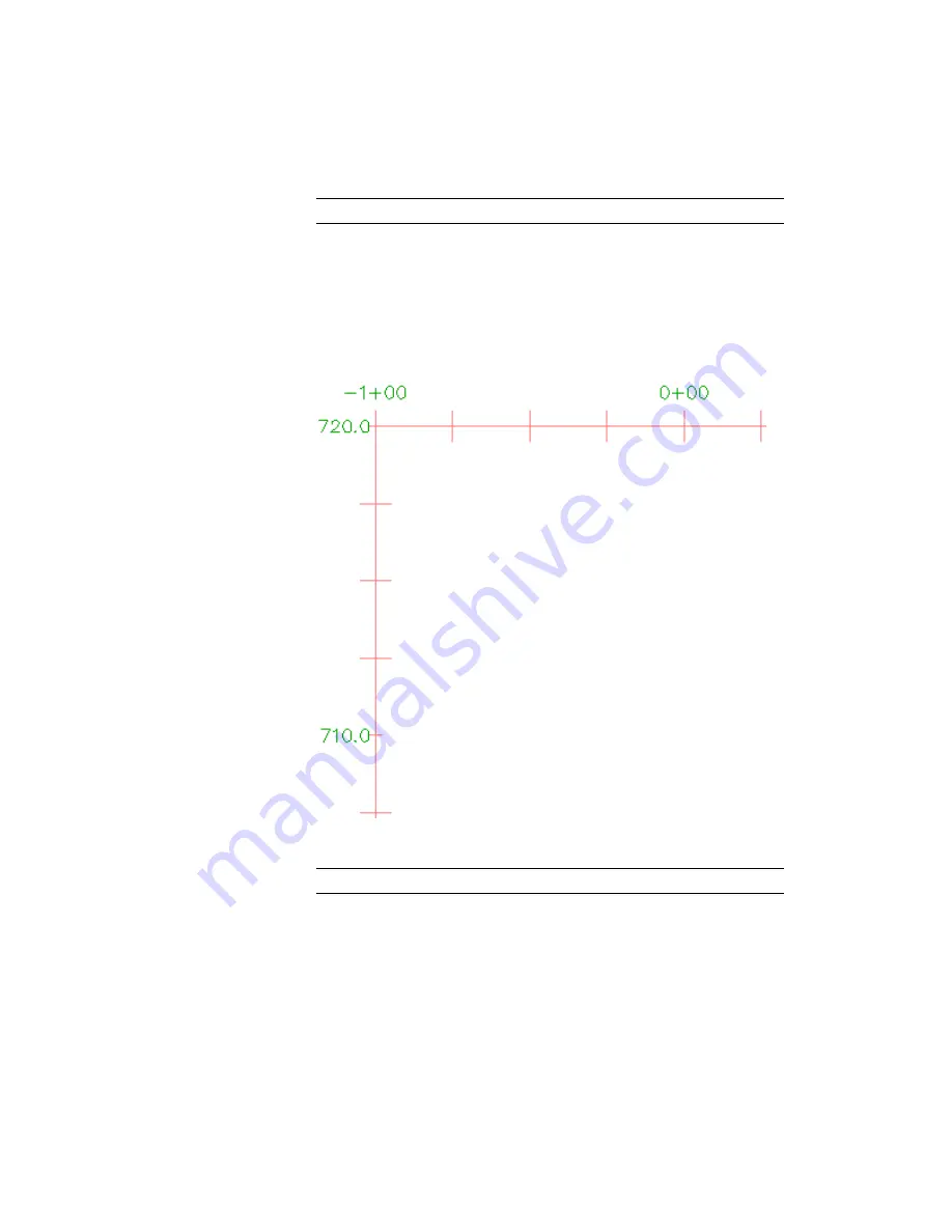
The bottom axis controls the major and minor grid spacing.
4
Under Major Tick Details, specify the following parameters:
■
Tick Size: 0.2500
■
Y Offset: 0.1000
5
Click Apply.
The major ticks are longer, and the station labels move up.
6
On the Vertical Axes tab, make sure Left is selected as the axis to control.
NOTE
The left axis controls the major and minor grid spacing.
7
Under Major Tick Details, specify the following parameters:
■
Tick Size: 0.2500
Exercise 1: Editing the Profile View Style | 309
Summary of Contents for AUTOCAD PLANT 3D 2011 - SYSTEM REQUIREMENTS
Page 1: ...AutoCAD Civil 3D 2011 Tutorials April 2010 ...
Page 58: ...46 ...
Page 70: ...58 ...
Page 73: ...Tutorial Creating and Adding Data to a Surface 61 ...
Page 140: ...128 ...
Page 378: ...7 Press Enter 366 Chapter 10 Parcels Tutorials ...
Page 385: ...8 Press Enter Exercise 2 Swinging One End of a Parcel Lot Line 373 ...
Page 432: ...420 ...
Page 470: ...458 ...
Page 506: ...494 Chapter 13 Corridors Tutorials ...
Page 580: ...568 ...
Page 668: ...656 ...
Page 678: ...23 Change your view to SW isometric 666 Chapter 18 Part Builder Tutorials ...
Page 679: ...24 Change your visual style to Conceptual Exercise 2 Defining the Manhole Geometry 667 ...
Page 706: ...694 Chapter 18 Part Builder Tutorials ...
Page 830: ...818 ...
Page 832: ...tutorial folder AutoCAD Civil 3D installation location Help Civil Tutorials 820 Glossary ...


