5
Click Apply.
The new data band is displayed at the bottom of the stack of data bands.
This data band labels the vertical geometry points of the first profile in
the list. In this case, the existing ground profile was selected by default.
You will change the referenced profile later in this exercise.
6
In the Profile View Properties dialog box, on the Bands tab, specify the
following parameters:
■
Band Type: Horizontal Geometry
■
Select Band Style: Curvature
■
Location: Bottom Of Profile View
7
Click Add.
8
Click Apply.
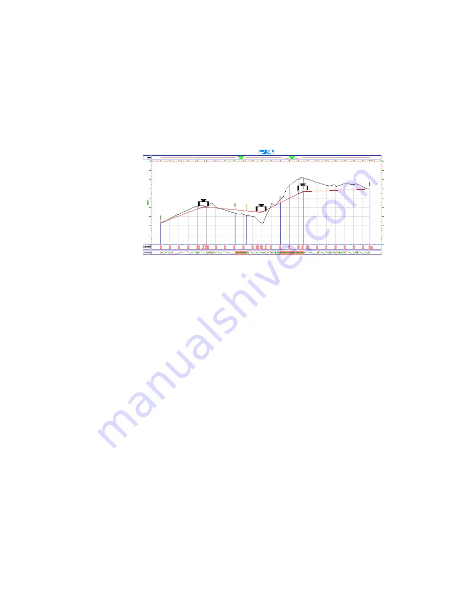
The horizontal geometry band is added to the bottom of the profile view
in the drawing. This data band is drawn in a different style from the one
along the top of the grid. However, both styles show the location of
horizontal curves and are labeled with basic engineering data about the
curves. These bands are useful for evaluating the design profile from a
drainage and safety point-of-view.
332 | Chapter 9 Profiles Tutorials
Summary of Contents for AUTOCAD PLANT 3D 2011 - SYSTEM REQUIREMENTS
Page 1: ...AutoCAD Civil 3D 2011 Tutorials April 2010 ...
Page 58: ...46 ...
Page 70: ...58 ...
Page 73: ...Tutorial Creating and Adding Data to a Surface 61 ...
Page 140: ...128 ...
Page 378: ...7 Press Enter 366 Chapter 10 Parcels Tutorials ...
Page 385: ...8 Press Enter Exercise 2 Swinging One End of a Parcel Lot Line 373 ...
Page 432: ...420 ...
Page 470: ...458 ...
Page 506: ...494 Chapter 13 Corridors Tutorials ...
Page 580: ...568 ...
Page 668: ...656 ...
Page 678: ...23 Change your view to SW isometric 666 Chapter 18 Part Builder Tutorials ...
Page 679: ...24 Change your visual style to Conceptual Exercise 2 Defining the Manhole Geometry 667 ...
Page 706: ...694 Chapter 18 Part Builder Tutorials ...
Page 830: ...818 ...
Page 832: ...tutorial folder AutoCAD Civil 3D installation location Help Civil Tutorials 820 Glossary ...


