4
In the Profile Layout Tools toolbar, ensure that Draw Tangents With
Curves
is selected.
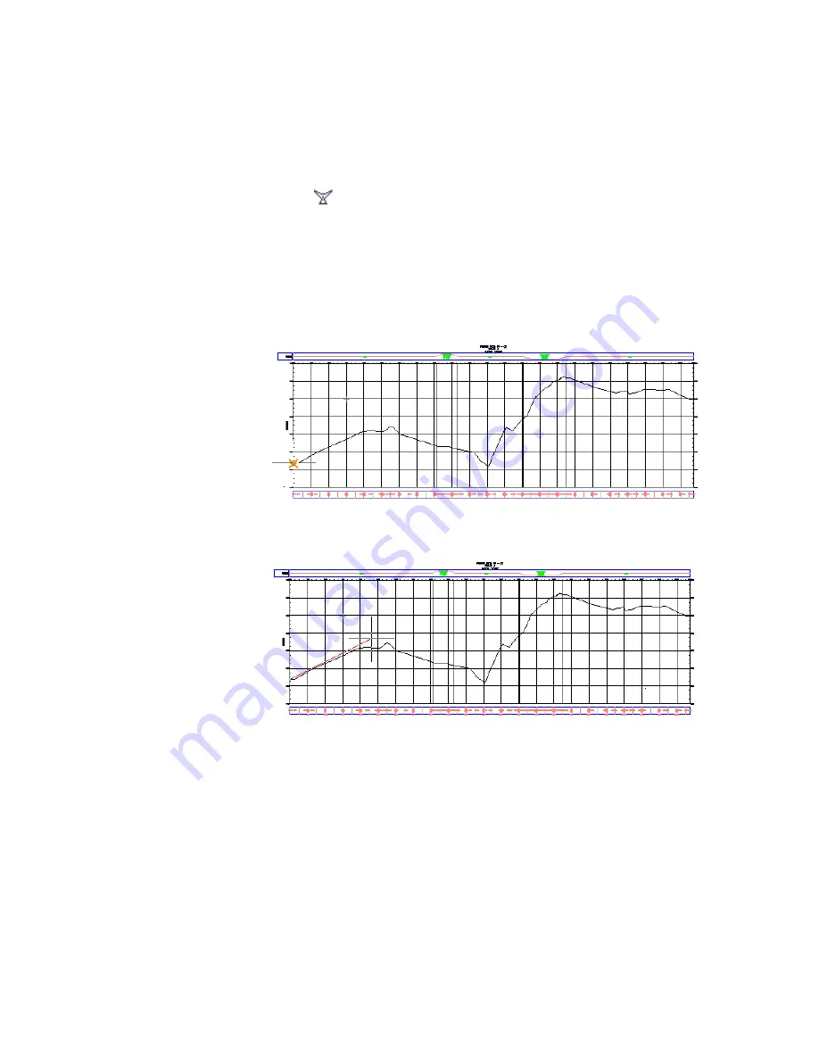
You are now ready to draw the layout profile by clicking in the drawing
at the proposed locations of PVIs. At each PVI, the application inserts a
curve. To be realistic, your line should follow the general profile of the
surface centerline. However, it can cut across steep hills and valleys to
outline a smoother road surface.
5
In the profile view, click the left side, near the centerline surface profile,
to start the layout profile.
6
Extend the line to the right and click at another location near the
centerline surface profile. Continue in this manner.
7
At the last point, right-click to end the profile. The layout profile is now
drawn and labeled.
Exercise 1: Creating a Layout Profile | 291
Summary of Contents for AUTOCAD PLANT 3D 2011 - SYSTEM REQUIREMENTS
Page 1: ...AutoCAD Civil 3D 2011 Tutorials April 2010 ...
Page 58: ...46 ...
Page 70: ...58 ...
Page 73: ...Tutorial Creating and Adding Data to a Surface 61 ...
Page 140: ...128 ...
Page 378: ...7 Press Enter 366 Chapter 10 Parcels Tutorials ...
Page 385: ...8 Press Enter Exercise 2 Swinging One End of a Parcel Lot Line 373 ...
Page 432: ...420 ...
Page 470: ...458 ...
Page 506: ...494 Chapter 13 Corridors Tutorials ...
Page 580: ...568 ...
Page 668: ...656 ...
Page 678: ...23 Change your view to SW isometric 666 Chapter 18 Part Builder Tutorials ...
Page 679: ...24 Change your visual style to Conceptual Exercise 2 Defining the Manhole Geometry 667 ...
Page 706: ...694 Chapter 18 Part Builder Tutorials ...
Page 830: ...818 ...
Page 832: ...tutorial folder AutoCAD Civil 3D installation location Help Civil Tutorials 820 Glossary ...


