8-16
1. Inspect wiring harness, three-prong connector,
lens, base, cap screws, and socket for damage.
2. Inspect all wires for corroding, pinching, and
cracking.
3. Inspect the bulb for wattage, voltage, and proper
operation.
INSTALLING
1. Place the assembly into position on the frame and
secure with torx-head cap screws and any washers.
2. Tighten the cap screws securely.
3. Route the wiring harness over the rear frame; then
connect the three-prong connector.
Seat
REMOVING/INSTALLING
1. To remove the seat, lift up on the latch release
(located at the rear of the seat). Raise the rear of
the seat and slide it rearward.
2. To lock the seat into position, slide the front of the
seat into the seat retainers and push down firmly
on the rear of seat. The seat should automatically
lock into position.
REMOVING/INSTALLING (TRV)
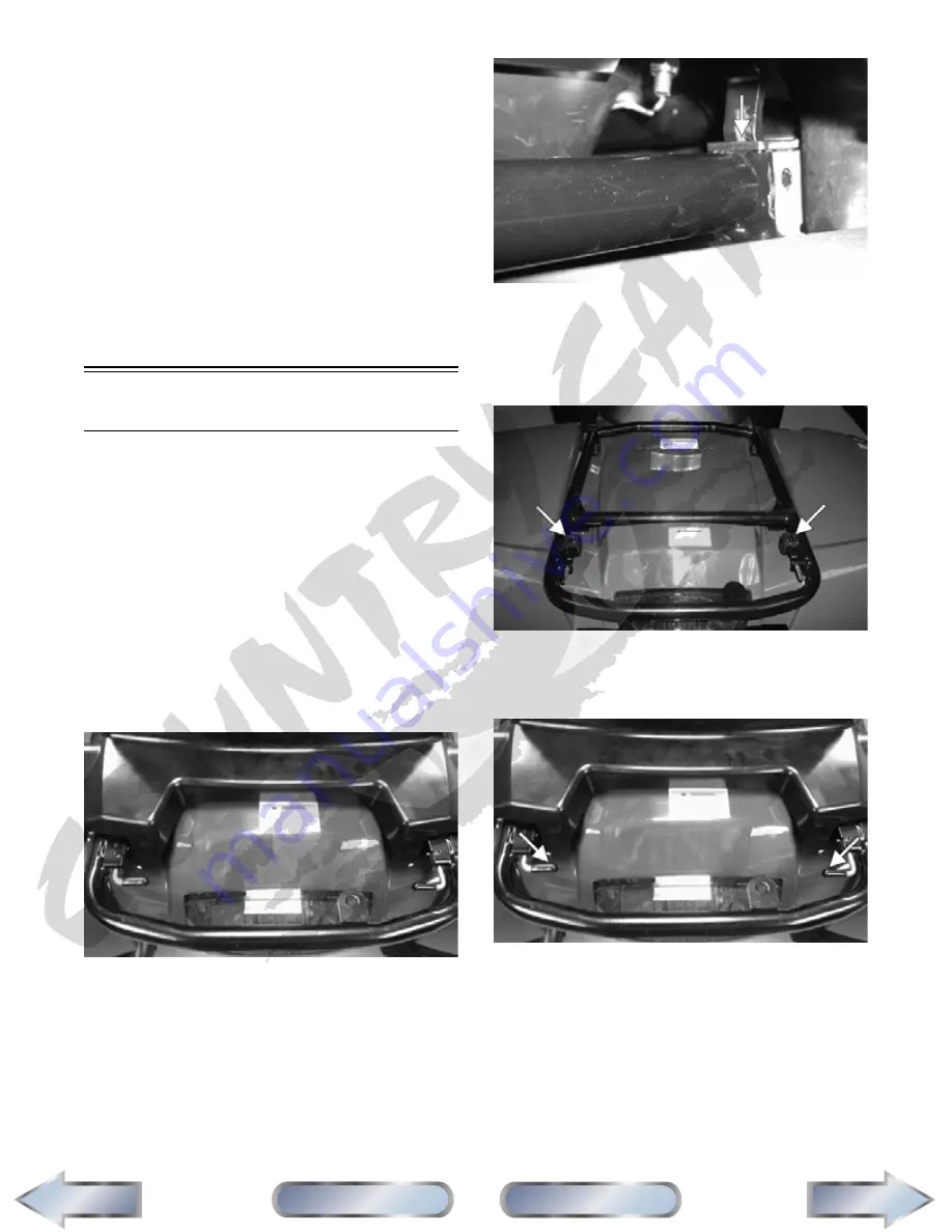
1. To remove the rear seat, pull the two latch handles
to the rear and rotate them to the vertical position.
CF226
2. Lift the rear of the seat up; then pull slightly to the
rear and lift the seat off the mountings.
CF227A
3. To lock the seat into position, engage the two front
mounting lugs into the mounting rack; then hold-
ing down firmly on the front of the seat, push the
seat forward until the rear tabs engage the rear
mounting latches.
CF229A
4. Lock the seat into position by pulling the two latch
handles to the rear and rotating them to the hori-
zontal position.
CF226A
NOTE: The rear seat must be removed prior to
removing the front seat.
5. To remove the front seat, pull the seat lock lever
up (located at the rear of the seat). Raise the rear
end of the seat and slide it rearward.
6. To lock the seat into position, slide the front of the
seat into the seat retainers and push down firmly
on rear of seat. The seat should automatically lock
into position.
Next
Back
Section
Table of Contents
Manual
Table of Contents


