System Installation
22
TPI-PRO (Total Presentation Interface)
If the PC is connected to Type-B USB port #4, then the video output on the PC must be connected
to INPUT 4 (inputs 3 & 4 available only on the TPI-PRO-4).
5.
Connect an HD-15 video cable from the output on the monitor to one of the VGA OUTPUT ports on the
TPI-PRO.
6.
Apply power to the TPI-PRO.
7.
Code a button on the touch monitor page to enable the pass-thru feature on a selected source input.
Toggling this coded panel button will enable/disable the pass-thru feature.
8.
Setup the TPI-PRO output resolution using the procedures in the
9.
Use the monitor’s video adjust buttons to align the incoming video signal to fit into the available screen
area. Initially positioning the incoming video can reduce the necessity of later adjustments (H-position,
V-position, H-size, etc.) through the RGB Setup page.
Using a Touch Monitor for Mouse/Touch Pass-Thru Control
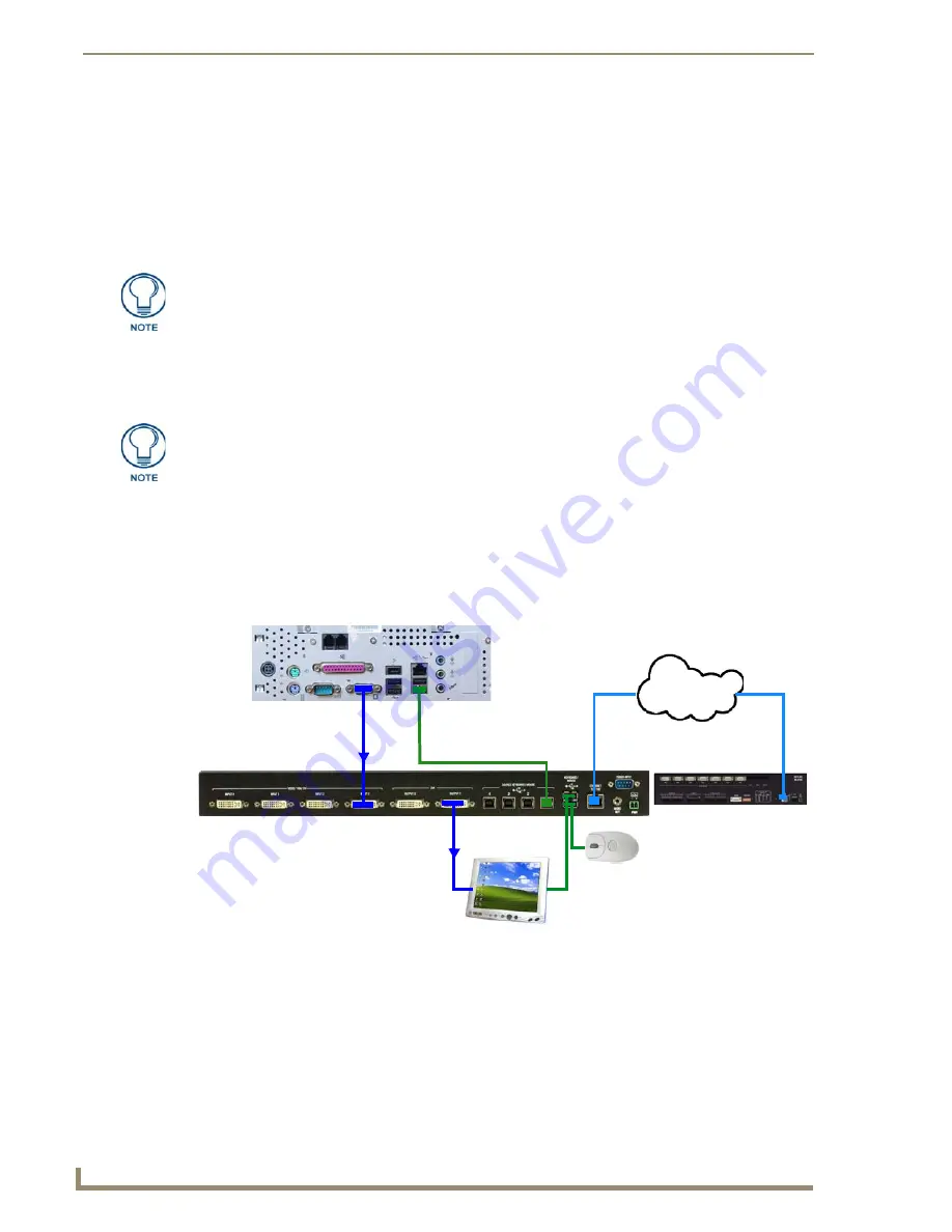
FIG. 27 illustrates a typical installation for using a touch monitor for mouse and touch pass-thru control.
Enabling Video Pass-Through Control on a Touch Monitor
To enable a touch response on a panel page being routed through a computer, you must establish pass-thru
control. Pass-thru control allows the TPI-PRO to act as a control bridge between a PC and a touch monitor.
The touch monitor control option is available only if a
Video Fill
has been applied to the panel page (in the
TPDesign4 (Touch Panel Design software application).
With the panel page open in TPDesign4:
1.
Select the
States
tab of the Properties Control Window.
You first must set the TPI-PRO to match the resolution of the computer’s video output
resolution, and then you must adjust the TPI-PRO to fit the available screen on the
monitor.
If the image generated from the TPI-PRO is slightly "off", adjust the image using the
monitor’s on-board video adjustment buttons.
If the TPI-PRO is power cycled, the video alignment settings established through the
Video and/or RGB pages will be reset, unless the adjusted values have been saved.
Refer to the Setup - Video Settings Page
for more information.
FIG. 27
Example 3: Using a Touch Monitor for Mouse / Touch Pass-Thru Control
PC
TPI OUTPUT 1 connects to VGA touch monitor
Touch Monitor
LAN
NetLinx Master
USB Mouse
Touch input USB connector on touch monitor
connects to KEYBOARD/MOUSE USB Port on TPI
(via USB cable)
Type-B USB cable connects the
PC and TPI (control is on panel
pages on the PC and displayed
on the touch monitor)
VGA output from PC
connects to TPI INPUT 1
Summary of Contents for TPI-PRO-4
Page 14: ...xii TPI PRO Total Presentation Interface Table of Contents ...
Page 76: ...TPI PRO DVI Configuration Pages 70 TPI PRO DVI Total Presentation Interface ...
Page 172: ...Terminal Telnet Commands 166 TPI PRO DVI Total Presentation Interface ...
Page 180: ...Upgrading Firmware 174 TPI PRO DVI Total Presentation Interface ...
Page 208: ...Supported Input and Output Modes 202 TPI PRO DVI Total Presentation Interface ...
Page 214: ...Appendix 208 TPI PRO DVI Total Presentation Interface ...
Page 217: ...Troubleshooting 203 TPI PRO Total Presentation Interface ...


