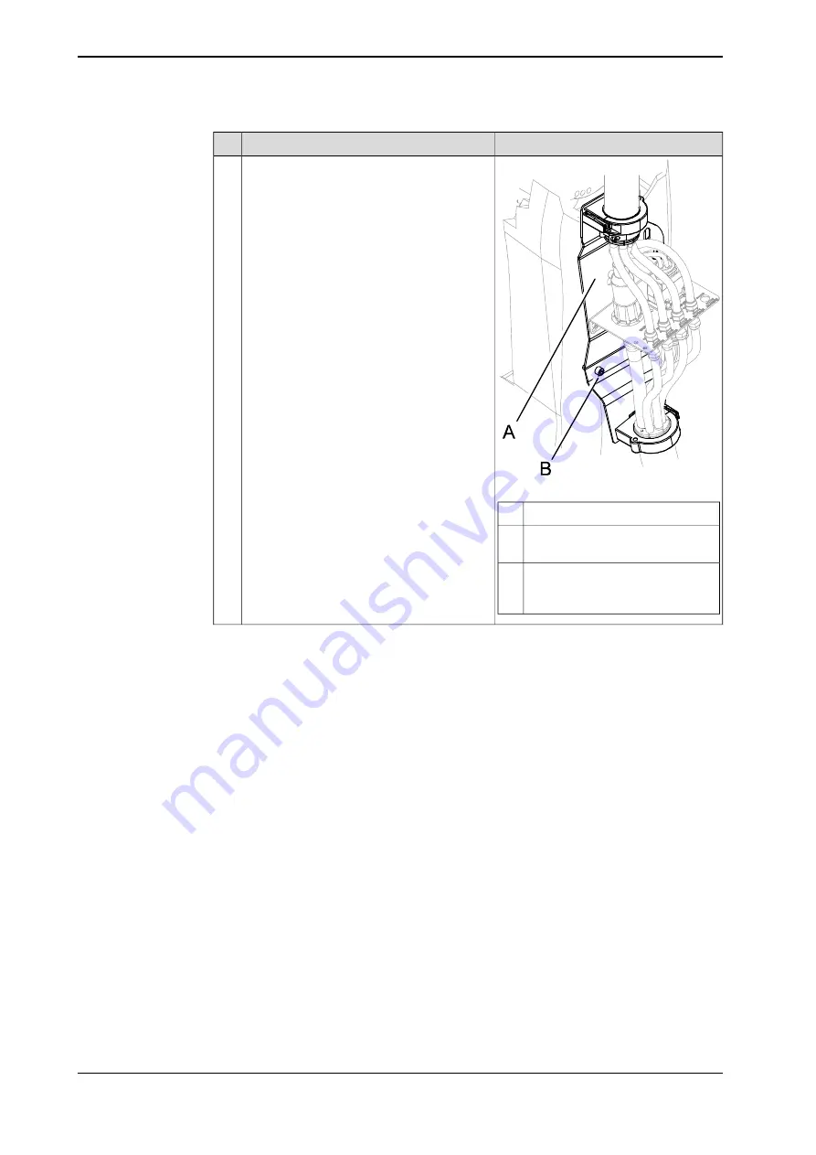
ABB DressPack IRB 6640 Product Manual Download Page 56

Note

Action

xx0700000327

Fit the lower arm plate to the lower arm with
its attachment screws.
Lock the screws with locking liquid.

6

Lower arm plate

A

Screw, M12x25, quality 8.8-A3F (4
pcs) (short upper arm)

B

Screws, M12x25 (2 pcs) and
M12x35 (2 pcs) with 2 washers,
quality 8.8-A3F (long upper arm)

C

Continues on next page

56

Product manual - DressPack/SpotPack IRB 6640

3HAC028638-001 Revision: K

© Copyright 2007-2018 ABB. All rights reserved.

2 Installation

2.2.3 Fitting the attachments of IRBDP MH2 LE and IRBDP SW2 LE

Continued

Summary of Contents for DressPack IRB 6640

Page 1: ...ROBOTICS Product manual DressPack SpotPack IRB 6640 ...

Page 2: ...Trace back information Workspace R18 1 version a9 Checked in 2018 03 22 Skribenta version 5 2 025 ...

Page 3: ...Product manual DressPack SpotPack IRB 6640 IRC5 Document ID 3HAC028638 001 Revision K Copyright 2007 2018 ABB All rights reserved ...

Page 4: ...BB for losses damages to persons or property fitness for a specific purpose or the like In no event shall ABB be liable for incidental or consequential damages arising from use of this manual and products described herein This manual and parts thereof must not be reproduced or copied without ABB s written permission Keep for future reference Additional copies of this manual may be obtained from AB...

Page 5: ...itting the attachments of IRBDP MH1 LI and MH3 UE 69 2 2 6 Fitting the attachments of IRBDP SW5 CE SpotPack Basic 78 2 2 7 Fitting the attachments of IRBDP SW6 MH6 UI LE Lean ID 93 2 2 8 Fitting the cable packages IRBDP MH2 LE and IRBDP SW2 LE 102 2 2 9 Fitting the cable packages IRBDP MH2 UE and IRBDP SW2 UE 107 2 2 10 Fitting the cable package IRBDP SW2 CE 118 2 2 11 Fitting the cable package IR...

Page 6: ...nternal MH dressing cable package IRBDP MH1 LI 239 4 2 6 Replacing the cable package IRBDP MH3 UE 243 4 2 7 Replacing the cable package IRBDP SW5 CE SpotPack Basic 247 4 2 8 Replacement process cable package IRBDP SW4 UI IRB66X0ID 265 4 2 9 Replacing the cable package IRBDP SW6 UI LE IRBDP MH6 UI LE Lean ID 275 4 2 10 Replacement of tension arm unit 278 4 2 11 Replacement of damper 280 4 2 12 Repl...

Page 7: ...pper arm MH IRBDP MH3 UE 350 7 9 DressPack for IRBDP MH2 CE and IRBDP SW2 CE 353 7 10 SpotPack Basic cable package IRBDP SW 5 CE 354 7 11 DressPack cable package for IRBDP SW6 LE UI and IRBDP MH6 LE UI Lean ID 356 7 12 Process cable package IRB66X0ID 357 7 13 Connection kits 358 7 14 7 th axis to base 359 7 15 DressPack floor standard 362 7 16 Customer signal power 363 7 17 DressPack Water and air...

Page 8: ...This page is intentionally left blank ...

Page 9: ... installation repair maintenance work Organization of chapters The manual is organized in the following chapters Contents Chapter Safety information that must be read through before performing any installation or service work on the robot Contains general safety aspects as well as more specific information on how to avoid personal injuries and damage to the product Safety Descriptions of mechanica...

Page 10: ...manuals for the manipulators and the controllers Note The document numbers that are listed for software documents are valid for RobotWare 6 Equivalent documents are available for RobotWare 5 Revisions Description Revision First edition The following has been added or changed The process cable package IRBDP SW 5 CE SpotPack Basic has been implemented throughout the manual Chapter Spotwelding Cabine...

Page 11: ...Text and illustration has been updated to better explain the import ance of the position of the protective sleeves on the upper arm of the cable packages IRBDP SW6 UI IRBDP MH6 UI See Preventive inspection DressPack upper arm on page 200 The quality of some illustrations has been updated for better under standing New number added in connection kits for Spare parts IRBDP SW6 LE UE and IRBDP MH6 LE ...

Page 12: ...in release R17 2 The following updates are done in this revision Updated list of applicable standards J Published in release R18 1 The following updates are made in this revision Clarified procedure for tension adjustment see Adjusting tension arm unit on page 299 Safety section restructured K 12 Product manual DressPack SpotPack IRB 6640 3HAC028638 001 Revision K Copyright 2007 2018 ABB All right...

Page 13: ...formation safety standards unit conversions screw joints lists of tools Spare parts list with corresponding figures or references to separate spare parts lists Circuit diagrams or references to circuit diagrams Technical reference manuals The technical reference manuals describe reference information for robotics products for example lubrication the RAPID language and system parameters Application...

Page 14: ...uals are aimed at those having first hand operational contact with the product that is production cell operators programmers and troubleshooters 14 Product manual DressPack SpotPack IRB 6640 3HAC028638 001 Revision K Copyright 2007 2018 ABB All rights reserved Product documentation Continued ...

Page 15: ...with a reference to the section where the equipment is listed with further information that is article number and dimensions The designation in the procedure for the component or attachment point corresponds to the designation in the referenced list The table below shows an example of a reference to a list of required equipment from a step in a procedure Note Illustration Action Art no is specifie...

Page 16: ... name Material handling MH Spot welding SW Generations The different generations of a DressPack is indicated with a generation number The number indicates the different design of each generation Some generations might not be available since it has been phased out 1 2 3 etc Sections The DressPack on the robot is supplied in different sections Section Product name Lower DressPack section L Upper Dre...

Page 17: ...essPack section Internal routing IRBDP SW 2 LE IRB DressPack Spot welding application Generation 2 Lower arm DressPack section External routing IRBDP SW 2 CE IRB DressPack Spot welding application Generation 2 Continuos DressPack section External routing Product manual DressPack SpotPack IRB 6640 17 3HAC028638 001 Revision K Copyright 2007 2018 ABB All rights reserved Product name principles Conti...

Page 18: ...This page is intentionally left blank ...

Page 19: ... by in experienced or non qualified personnel Foreign objects Force majeure Nation region specific regulations To protect personnel the complete system must be designed and installed in accordance with the safety requirements set forth in the standards and regulations of the country where the robot is installed To be observed by the supplier of the complete system The integrator is responsible tha...

Page 20: ...mine the maximum speed from the maximum velocities of the robot axes and from the position at which the robot is working in the work cell see the section Robot motion in the Product specification Also consider the maximum possible impact caused by a breaking or malfunctioning rotating tool or other device fitted to the robot Safe handling Users shall not be exposed to hazards including slipping tr...

Page 21: ...hrough welding riveting or drilling of new holes into the castings The strength could be affected CAUTION Ensure that a gripper is prevented from dropping a work piece if such is used Product manual DressPack SpotPack IRB 6640 21 3HAC028638 001 Revision K Copyright 2007 2018 ABB All rights reserved 1 Safety 1 1 1 Limitation of liability Continued ...

Page 22: ...rotective stops and emergency stops are described in the product manual for the controller 22 Product manual DressPack SpotPack IRB 6640 3HAC028638 001 Revision K Copyright 2007 2018 ABB All rights reserved 1 Safety 1 1 2 Protective stop and emergency stop ...

Page 23: ...ote Use a CARBON DIOXIDE CO2 extinguisher in the event of a fire in the manipulator or controller Product manual DressPack SpotPack IRB 6640 23 3HAC028638 001 Revision K Copyright 2007 2018 ABB All rights reserved 1 Safety 1 2 1 Fire extinguishing ...

Page 24: ...fore proceeding work Note Switch off all main power switches in a MultiMove system Spot welding cabinet Wait for 5 minutes to let the capacitors discharge after the power has been switched off DANGER Even if the main switch is switched off the capacitors can cause electric shock if not given the time to discharge 24 Product manual DressPack SpotPack IRB 6640 3HAC028638 001 Revision K Copyright 200...

Page 25: ...k Make sure that no one else can turn on the power to the controller and robot while you are working with the system A good method is to remove the power cable to the controller If the robot is installed at a height hanging or other than standing directly on the floor there may be additional risks than those for a robot standing directly on the floor Energy stored in the robot for the purpose of c...

Page 26: ... to the robot Connection of external safety devices Apart from the built in safety functions the robot is also supplied with an interface for the connection of external safety devices An external safety function can interact with other machines and peripheral equipment via this interface This means that control signals can act on safety signals received from the peripheral equipment as well as fro...

Page 27: ...s powered up 2 Verify that any safety equipment installed to secure the position or restrict the robot motion during service activity is removed 3 Verify that the fixture and work piece are well secured if applicable 4 Install all safety equipment properly 5 Make sure all personnel are standing at a safe distance from the robot and is out of its reach behind safety fences or similar 6 If maintenan...

Page 28: ...r switches to the MOTORS OFF state To ensure safe use of the teach pendant the following must be implemented The enabling device must never be rendered inoperational in any way During programming and testing the enabling device must be released as soon as there is no need for the robot to move Anyone entering the working space of the robot must always hold the teach pendant This is to prevent anyo...

Page 29: ...ks IRC5 controller A danger of high voltage is associated with for example the following parts Be aware of stored electrical energy DC link Ultracapacitor bank unit in the controller Units such as I O modules can be supplied with power from an external source The main supply main switch The transformers The power unit The control power supply 230 VAC The rectifier unit 262 400 480 VAC and 400 700 ...

Page 30: ...en if the robot system is in the OFF position Power supply cables which are in motion during the working process may be damaged 30 Product manual DressPack SpotPack IRB 6640 3HAC028638 001 Revision K Copyright 2007 2018 ABB All rights reserved 1 Safety 1 3 4 Risks associated with live electric parts Continued ...

Page 31: ... at some distance to feel if heat is radiating from the potentially hot component before actually touching it Wait until the potentially hot component has cooled if it is to be removed or handled in any other way Do not put anything on hot metal surfaces e g paper or plastic Product manual DressPack SpotPack IRB 6640 31 3HAC028638 001 Revision K Copyright 2007 2018 ABB All rights reserved 1 Safety...

Page 32: ...e released in the complete pneumatic or hydraulic systems before starting to repair them Work on hydraulic equipment may only be performed by persons with special knowledge and experience of hydraulics All pipes hoses and connections have to be inspected regularly for leaks and damage Damage must be repaired immediately Splashed oil may cause injury or fire Safe design Gravity may cause any parts ...

Page 33: ...re water or battery vent explosion fire may follow depending upon the circumstances Note Appropriate disposal regulations must be observed Safe handling Use safety glasses when handling the batteries In the event of leakage wear rubber gloves and chemical apron In the event of fire use self contained breathing apparatus Do not short circuit recharge puncture incinerate crush immerse force discharg...

Page 34: ...n Description Warning Make sure that protective gear like goggles and gloves are al ways worn during this activity Changing and draining gearbox oil or grease may require hand ling hot lubricant heated up to 90 C Hot oil or grease Make sure that protective gear like goggles and gloves are al ways worn When working with gearbox lub ricant there is a risk of an allergic reaction Allergic reaction Op...

Page 35: ...heat up the oil Warm oil drains quicker than cold oil Heat up the oil After filling verify that the level is correct The specified amount of oil or grease is based on the total volume of the gearbox When changing the lubricant the amount refilled may differ from the specified amount depending on how much has previously been drained from the gearbox Specified amount de pends on drained volume When ...

Page 36: ...he instructions are not followed that can lead to serious injury pos sibly fatal and or great damage to the product It applies to warnings that apply to danger with for example contact with high voltage electrical units explosion or fire risk risk of poisonous gases risk of crushing impact fall from height etc WARNING xx0100000002 Warns for electrical hazards which could result in severe personal ...

Page 37: ...0000004 Describes where to find additional information or how to do an operation in an easier way TIP xx0100000098 Product manual DressPack SpotPack IRB 6640 37 3HAC028638 001 Revision K Copyright 2007 2018 ABB All rights reserved 1 Safety 1 4 1 Safety signals in the manual Continued ...

Page 38: ...an and French Symbols on safety labels Description Symbol Warning xx0900000812 Warns that an accident may occur if the instructions are not followed that can lead to serious injury possibly fatal and or great damage to the product It applies to warnings that apply to danger with for example contact with high voltage electrical units explosion or fire risk risk of poisonous gases risk of crushing i...

Page 39: ...sassemble xx0900000815 Disassembling this part can cause injury Extended rotation xx0900000814 This axis has extended rotation working area compared to standard Brake release xx0900000808 Pressing this button will release the brakes This means that the robot arm can fall down Continues on next page Product manual DressPack SpotPack IRB 6640 39 3HAC028638 001 Revision K Copyright 2007 2018 ABB All ...

Page 40: ... the bolts are not securely fastened xx1500002402 Crush xx0900000817 Risk of crush injuries Continues on next page 40 Product manual DressPack SpotPack IRB 6640 3HAC028638 001 Revision K Copyright 2007 2018 ABB All rights reserved 1 Safety 1 4 2 Safety symbols on product labels Continued ...

Page 41: ...300001087 Moving robot 1 2 3 4 5 6 xx0900000819 The robot can move unexpectedly xx1000001141 1 2 3 4 xx1500002616 Continues on next page Product manual DressPack SpotPack IRB 6640 41 3HAC028638 001 Revision K Copyright 2007 2018 ABB All rights reserved 1 Safety 1 4 2 Safety symbols on product labels Continued ...

Page 42: ...fting of robot xx0900000822 Oil xx0900000823 Can be used in combination with prohibition if oil is not allowed Mechanical stop xx0900000824 Continues on next page 42 Product manual DressPack SpotPack IRB 6640 3HAC028638 001 Revision K Copyright 2007 2018 ABB All rights reserved 1 Safety 1 4 2 Safety symbols on product labels Continued ...

Page 43: ...part is pressurized Usually contains additional text with the pressure level Shut off with handle xx0900000827 Use the power switch on the controller Do not step xx1400002648 Warns that stepping on these parts can cause damage to the parts Product manual DressPack SpotPack IRB 6640 43 3HAC028638 001 Revision K Copyright 2007 2018 ABB All rights reserved 1 Safety 1 4 2 Safety symbols on product lab...

Page 44: ...This page is intentionally left blank ...

Page 45: ...chapters Sections The installation chapter is divided in the following sections Fitting DressPack cable package attachments Fitting DressPack cable packages DressPack floor cable Water and air unit Product manual DressPack SpotPack IRB 6640 45 3HAC028638 001 Revision K Copyright 2007 2018 ABB All rights reserved 2 Installation 2 1 Introduction ...

Page 46: ...nts of the robot will be limited The position of process cable support axis 6 is important to take in consideration when optimizing the possible movements of the robot Note Maximum movement of axis 5 is 110 For more information please contact local ABB Effects on armload and performance Note The extra weight of the DressPack SpotPack products will affect the armload data and the performance of the...

Page 47: ...BDP MH1 LI and IRBDP MH3 UE divided A IRBDP SW2 LE UE IRBDP MH2 LE UE divided B IRBDP SW2 CE continuous C IRBDP SW6 MH6 LE D IRBDP SW6 MH6 UI E Cable package IRBDP MH1 LI lower internal F Connection plate G Cable package IRBDP MH3 UE upper external H Cable package IRBDP SW2 LE IRBDP MH2 LE J Continues on next page Product manual DressPack SpotPack IRB 6640 47 3HAC028638 001 Revision K Copyright 20...

Page 48: ... SW2 LE on page 51 Fitting the attachments of the IRBDP SW2 CE lower end 1 See Fitting the attachments of IRBDP MH2 UE and IRBDP SW2 UE on page 58 Fitting the attachments of the IRBDP SW2 CE upper end 2 See Fitting the cable package IRBDP SW2 CE on page 107 Fitting the cable package IRBDP SW2 CE 3 This is detailed in section Inspection DressPack lower arm on page 145 Inspecting the lower arm equip...

Page 49: ...ing the cable package IRBDP MH1 LI on page 118 Fitting the cable package IRBDP MH1 LI 5 This is detailed in section Fitting the cable packages IRBDP MH2 LE and IRBDP SW2 LE on page 93 Fitting the cable packages IRBDP MH2 LE and SW2 LE 6 This is detailed in section Fitting the cable packages IRBDP MH2 UE and IRBDP SW2 UE on page 102 Fitting the cable packages IRBDP MH2 UE and SW2 UE 7 This is detai...

Page 50: ...ble pack age IRBDP SW5 CE SpotPack Basic on page 128 Fitting the cable package IRBDP SW5 CE SpotPack Basic 2 Detailed in section Inspection during pro gramming and test running on page 161 Inspection during programming and test running 3 Detailed in section Adjustment of the cable package IRBDP SW5 CE SpotPack Basic on page 156 Adjustments of the process cable pack age IRBDP SW5 CE SpotPack Basic ...

Page 51: ...E and IRBDP SW2 LE The location of the attachments of the cable packages IRBDP MH2 LE and SW2 LE are shown in the figure xx0700000323 Strap A Velcro strap B Bracket axis 1 C Lower arm plate D Connection plate part of process cable package E Gripping clamps F Process cable package G Side bracket balancing device incl lower bracket H Continues on next page Product manual DressPack SpotPack IRB 6640 ...

Page 52: ...e number Consumable Loctite 243 For locking the screws 3HAB7116 1 Locking liquid Procedure This procedure describes how to install the attachments for the cable packages IRBDP MH2 LE and SW2 LE The screws are supplied with the kit Note Action DANGER Turn off all electric power supply hydraulic pressure supply air pressure supply to the robot before entering the robot work ing area 1 Continues on n...

Page 53: ... attachment screws Lock the screws with locking liquid 3 Side bracket balancing device incl lower bracket A Screw side bracket M10x16 quality 8 8 A3F 4 pcs B Screw lower bracket M10x16 quality 8 8 A3F 2 pcs C Continues on next page Product manual DressPack SpotPack IRB 6640 53 3HAC028638 001 Revision K Copyright 2007 2018 ABB All rights reserved 2 Installation 2 2 3 Fitting the attachments of IRBD...

Page 54: ... A Gripping clamp B Side bracket balancing device C Screw gripping clamp M8x16 quality 8 8 A2F 2 pcs Screw lower bracket M10x16 quality 8 8 A3F 2 pcs xx0700000334 Side bracket balancing device A Lower bracket B Continues on next page 54 Product manual DressPack SpotPack IRB 6640 3HAC028638 001 Revision K Copyright 2007 2018 ABB All rights reserved 2 Installation 2 2 3 Fitting the attachments of IR...

Page 55: ...to the right 5 Lower bracket SW and MH intern al A Lower bracket MH external B Lower arm bracket C Continues on next page Product manual DressPack SpotPack IRB 6640 55 3HAC028638 001 Revision K Copyright 2007 2018 ABB All rights reserved 2 Installation 2 2 3 Fitting the attachments of IRBDP MH2 LE and IRBDP SW2 LE Continued ...

Page 56: ...12x25 quality 8 8 A3F 4 pcs short upper arm B Screws M12x25 2 pcs and M12x35 2 pcs with 2 washers quality 8 8 A3F long upper arm C Continues on next page 56 Product manual DressPack SpotPack IRB 6640 3HAC028638 001 Revision K Copyright 2007 2018 ABB All rights reserved 2 Installation 2 2 3 Fitting the attachments of IRBDP MH2 LE and IRBDP SW2 LE Continued ...

Page 57: ... Gripping clamp A Screw M8x25 quality 8 8 A2F 2 pcs B Washer 2 holes C Washer 2 pcs Locking nuts 2 pcs xx0700000320 Measurement 24 mm A Oval holes for attachment screws gripping clamp B Lower arm plate C Product manual DressPack SpotPack IRB 6640 57 3HAC028638 001 Revision K Copyright 2007 2018 ABB All rights reserved 2 Installation 2 2 3 Fitting the attachments of IRBDP MH2 LE and IRBDP SW2 LE Co...

Page 58: ...tinuous Location of the attachments of IRBDP MH2 UE and IRBDP SW2 UE The location of the attachments of the cable packages IRBDP MH2 UE and SW2 UE is shown in the figure xx0700000324 Strap and strap holder A Tension arm unit B Ball joint housing tension arm C Process cable package D Continues on next page 58 Product manual DressPack SpotPack IRB 6640 3HAC028638 001 Revision K Copyright 2007 2018 A...

Page 59: ...nces to these procedures in the step by step instruc tions below Required consumables Note Article number Consumable Loctite 243 3HAB7116 1 Locking liquid For locking the gripping clamps Procedure This procedure describes how to install the attachments for the cable packages IRBDP MH2 UE and SW2 UE The screws are supplied with the kit Note Action DANGER Turn off all electric power supply hydraulic...

Page 60: ...with locking liquid 2 Art no is specified in section Required equipment on page 59 xx0500001430 Parts A Gripping clamp B Attachment screws M8x16 quality 8 8 A2F 2 pcs C Washer 2 holes Continues on next page 60 Product manual DressPack SpotPack IRB 6640 3HAC028638 001 Revision K Copyright 2007 2018 ABB All rights reserved 2 Installation 2 2 4 Fitting the attachments of IRBDP MH2 UE and IRBDP SW2 UE...

Page 61: ... ory to lift the tension arm unit 3 Art no is specified in section Required equipment on page 59 B B A C xx0500001433 Lock the screws with locking liquid Parts A Tension arm unit B Attachment screws M12x25 quality 8 8 A3F 4 pcs C Ø10 mm hole Continues on next page Product manual DressPack SpotPack IRB 6640 61 3HAC028638 001 Revision K Copyright 2007 2018 ABB All rights reserved 2 Installation 2 2 ...

Page 62: ...assembly forwards until it is seated against the rear of the turning disk Note Lock the M10x40 screws with locking liquid Do not use locking liquid on the M12x80 screws Tightening torque M12x80 screws 70 Nm 4 Note Make sure there are equal gaps between clamp and support of the process cable support axis 6 62 Product manual DressPack SpotPack IRB 6640 3HAC028638 001 Revision K Copyright 2007 2018 A...

Page 63: ...E Bracket axis 1 F Gripping clamps G Bracket left H Connection plate J Required tools Note Article number Equipment The contents are defined in sec tion Toolkits DressPack Spot Pack on page 335 3HAC17290 7 Standard toolkit DressPack Spot Pack Required spare parts Note Article number Spare part Material set cable package IRBDP MH1 LI Continues on next page Product manual DressPack SpotPack IRB 6640...

Page 64: ...ote Action DANGER Turn off all electric power supply hydraulic pressure supply air pressure supply to the robot before entering the robot working area 1 Lock screws with Loctite 243 xx0700000338 Fit the bracket axis 1 on the frame with its three attachment screws M10x16 quality 8 8 A3F 2 Parts A Bracket axis 1 Continues on next page 64 Product manual DressPack SpotPack IRB 6640 3HAC028638 001 Revi...

Page 65: ...uid 3 Parts A Straps B Velcro straps C Rubber clamp with bracket D Side bracket balancing device Screw M10x16 quality 8 8 A3F 4 pcs E Lower bracket Continues on next page Product manual DressPack SpotPack IRB 6640 65 3HAC028638 001 Revision K Copyright 2007 2018 ABB All rights reserved 2 Installation 2 2 5 Fitting the attachments of IRBDP MH1 LI and MH3 UE Continued ...

Page 66: ... right 4 Parts A Lower bracket SW MH intern al B Lower bracket MH external C Lower arm bracket Screw M10x16 quality 8 8 A3F 2 pcs Art no is specified in Required tools on page 63 xx1000000119 Fit the cable guide on the upper arm 5 Parts A Cable guide Continues on next page 66 Product manual DressPack SpotPack IRB 6640 3HAC028638 001 Revision K Copyright 2007 2018 ABB All rights reserved 2 Installa...

Page 67: ...DANGER Turn off all electric power supply hydraulic pressure supply air pressure supply to the robot before entering the robot working area 1 xx0700000366 Fit bracket right with its attachment screws M8x16 quality 8 8 A2F 2 pcs Lock screws with locking liquid Screws are supplied with the kit 2 Parts A Bracket right Art no is specified in Required tools on page 63 Continues on next page Product man...

Page 68: ...n the bracket left with its attachment screws M8x16 quality 8 8 A2F 2 pcs Lock screw with locking liquid Screws are supplied with the kit 4 Parts A Bracket left B Protection hose C Gripping clamp D Rubber clamp with bracket Art no is specified in Required tools on page 63 68 Product manual DressPack SpotPack IRB 6640 3HAC028638 001 Revision K Copyright 2007 2018 ABB All rights reserved 2 Installat...

Page 69: ...0000067 Bracket axis 1 A Side bracket balancing cylinder B Lower bracket Spiral hose clamp C Lower arm plate Spiral hose clamp fitted at lower holes D Gripping clamp E Continues on next page Product manual DressPack SpotPack IRB 6640 69 3HAC028638 001 Revision K Copyright 2007 2018 ABB All rights reserved 2 Installation 2 2 6 Fitting the attachments of IRBDP SW5 CE SpotPack Basic ...

Page 70: ...applicable to IRB 7600 J Required equipment Note Part no Equipment The contents are defined in section Toolkits DressPack SpotPack on page 335 3HAC17290 7 Standard toolkit DressPack SpotPack These procedures include references to the tools required Other tools and procedures may be required See references to these procedures in the step by step instructions below Continues on next page 70 Product ...

Page 71: ...wer supply hydraulic pressure supply air pressure supply to the robot before entering the robot working area 1 xx0700000338 Fit the bracket axis 1 on the frame with its at tachment screws M10x16 quality 8 8 A3F 3 pcs Lock screws with locking liquid 2 Parts A Bracket axis 1 Continues on next page Product manual DressPack SpotPack IRB 6640 71 3HAC028638 001 Revision K Copyright 2007 2018 ABB All rig...

Page 72: ... supplied with the kit 3 Parts A Side bracket balancing cylin der B Attachment screws M10x16 quality 8 8 A3F 4 pcs Continues on next page 72 Product manual DressPack SpotPack IRB 6640 3HAC028638 001 Revision K Copyright 2007 2018 ABB All rights reserved 2 Installation 2 2 6 Fitting the attachments of IRBDP SW5 CE SpotPack Basic Continued ...

Page 73: ...0800000065 Variants IRB 6640 SW 2 75 A Side bracket balancing cylin der B Lower bracket Spiral hose clamp C Attachment screw M10x16 quality 8 8 A3F 2 pcs Note The lower bracket is fitted differently depending on robot variant See fig ures above Shown in the figure Location of the attachments on page 69 Fit the spiral hose clamp on the bottom lower bracket 5 Continues on next page Product manual Dr...

Page 74: ...r arm C Lower arm xx0800000073 Fit the gripping clamp on the lower arm plate with attachment screws M8x25 quality 8 8 A2F 2 pcs washer 2 holes Lock screws with locking liquid 7 Parts A Gripping clamp B Washer 2 holes C Attachment screws M8x25 quality 8 8 A2F 2 pcs D Lower arm plate Continues on next page 74 Product manual DressPack SpotPack IRB 6640 3HAC028638 001 Revision K Copyright 2007 2018 AB...

Page 75: ... 3 bracket to the armhouse with its attachment screws Lock screws with locking liquid 2 Parts A Axis 3 bracket Locking liquid is specified in Required equipment on page 70 xx0800000076 Fit the adjustable bracket to the axis 3 bracket with its brackets and attachment screws Lock screws with locking liquid 3 Parts A Adjustable bracket B Bracket C Axis 3 bracket Continues on next page Product manual ...

Page 76: ...Attachment screw M10x25 quality 8 8 A3F 2 pcs D Angled clamp bracket E Washer 2 holes F Attachment screw M8x16 quality 8 8_A2F 2 pcs G Gripping clamp xx0800000108 Fit the ball joint housing to the adjustable bracket with the bracket and its attachment screws and washer 2 holes Note Do not secure the attachment screws M10x25 at this point It must still be possible to move the gripping clamp back an...

Page 77: ...e 70 Shown in the figure Location of upper attachments on page 70 Fit the ball joint housing the harness support axis 6 with its attachment screws Lock screws with locking liquid 7 Locking liquid is specified in Required equipment on page 70 Product manual DressPack SpotPack IRB 6640 77 3HAC028638 001 Revision K Copyright 2007 2018 ABB All rights reserved 2 Installation 2 2 6 Fitting the attachmen...

Page 78: ...f the variants are shown in the figures The figure shows the attachments of the cable packages IRBDP SW6 LE and IRBDP MH6 LE xx1200000031 Cable guide see enlarged image A Housing lower part fitted on bracket B Ball joint housing fitted on lower arm bracket C Continues on next page 78 Product manual DressPack SpotPack IRB 6640 3HAC028638 001 Revision K Copyright 2007 2018 ABB All rights reserved 2 ...

Page 79: ...t and tube inside upper arm B Housing lower part C Upper arm bracket D Housing lower part E Bearing housing F Wrist protection cover G Mounting plate axis 3 Not visible in this view H Housing lower part I Connection plate J Adjustable axis 6 brackets K Continues on next page Product manual DressPack SpotPack IRB 6640 79 3HAC028638 001 Revision K Copyright 2007 2018 ABB All rights reserved 2 Instal...

Page 80: ...ting the cable attachments IRBDP SW6 LE and IRBDP MH6 LE Use this procedure to fit the cable attachments of the cable packages IRBDP SW6 LE and IRBDP MH6 LE Note Action Move the robot to a comfortable position for fitting the cable attachments on the lower arm 1 DANGER Turn off all electric power supply hydraulic pressure supply air pressure supply to the robot before entering the robot working ar...

Page 81: ...te 243 4 Attachment screws M12x25 quality 8 8 A3F 2 2 pcs xx1200000026 Fit the side bracket balancing cylinder with the lower bracket already fitted Lock screws with locking liquid Loctite 243 5 Attachment screws M10x16 quality 8 8 A3F 4 pcs Continues on next page Product manual DressPack SpotPack IRB 6640 81 3HAC028638 001 Revision K Copyright 2007 2018 ABB All rights reserved 2 Installation 2 2 ...

Page 82: ...g liquid Loctite 243 7 Attachment screws M12x25 quality 8 8 A2F 2 pcs xx1200000030 Fit the cable guide Lock screws with locking liquid Loctite 243 8 Attachment screws M8x25 quality 8 8 A2F 2 pcs washers Continues on next page 82 Product manual DressPack SpotPack IRB 6640 3HAC028638 001 Revision K Copyright 2007 2018 ABB All rights reserved 2 Installation 2 2 7 Fitting the attachments of IRBDP SW6 ...

Page 83: ...acket Attachment screws fitted from inside Se cure the wrist protection cover to the upper arm bracket with the nuts from the outside 3 Attachment screws and nuts M6x10 quality 8 8 A2F 2 pcs nuts M6 quality steel 8 A2F 2 pcs xx1200000041 Remove two M6 screws securing the wrist cover and replace them with distance screws with flange The second screw is placed diagonally below the screw shown Lock d...

Page 84: ...8 8 A2F 2 pcs washers 2 pcs xx1200000039 Fit the bearing housing on the upper arm bracket Lock screws with locking liquid Loctite 243 6 Attachment screws M8x12 quality 8 8 A2F 2 pcs Continues on next page 84 Product manual DressPack SpotPack IRB 6640 3HAC028638 001 Revision K Copyright 2007 2018 ABB All rights reserved 2 Installation 2 2 7 Fitting the attachments of IRBDP SW6 MH6 UI LE Lean ID Con...

Page 85: ...teps followed 8 Note If it is not possible to lock the adjustable bracket 2 2 in its most forward position by following the instructions below then move the athe bracket 2 2 as far forward as possible If this is the case the screw shown in the figure is not needed and shall not be used 9 Continues on next page Product manual DressPack SpotPack IRB 6640 85 3HAC028638 001 Revision K Copyright 2007 2...

Page 86: ...is now locked in its most forward position 11 Attachment screw M8x16 quality 8 8 A2F xx1200000155 Secure the adjustable braket 2 2 with the screw shown in the figure Lock the screw with locking liquid Loctite 243 12 Attachment screw M8x16 quality 8 8 A2F Continues on next page 86 Product manual DressPack SpotPack IRB 6640 3HAC028638 001 Revision K Copyright 2007 2018 ABB All rights reserved 2 Inst...

Page 87: ... A A B xx1200000118 A Holes for attachment screws B Position where to fit velcro strap Attachment screws Only valid with upper arm extension Fit the extension plate Lock screws with locking liquid Loctite 243 xx1200000120 16 M8x16 quality 8 8 A2F 2 pcs Continues on next page Product manual DressPack SpotPack IRB 6640 87 3HAC028638 001 Revision K Copyright 2007 2018 ABB All rights reserved 2 Instal...

Page 88: ... 8 A2F 3 pcs xx1200000043 Insert the tube into the arm tube and fit it into the insert 2 xx1200000162 Mount the two parts of the tube guiding ring 3 Pan head screw ST3 9x16 2 pcs Continues on next page 88 Product manual DressPack SpotPack IRB 6640 3HAC028638 001 Revision K Copyright 2007 2018 ABB All rights reserved 2 Installation 2 2 7 Fitting the attachments of IRBDP SW6 MH6 UI LE Lean ID Contin...

Page 89: ...house cover Lock screws with locking liquid Loctite 243 Note Check that the tube is being fitted correctly in both ends when fitting the cover 5 Attachment screws M6x16 quality 8 8 A2F 3 pcs Continues on next page Product manual DressPack SpotPack IRB 6640 89 3HAC028638 001 Revision K Copyright 2007 2018 ABB All rights reserved 2 Installation 2 2 7 Fitting the attachments of IRBDP SW6 MH6 UI LE Le...

Page 90: ...quality 8 8 A2F 2 pcs xx1200000023 Fit the housing lower part one on each of the brackets for cable clamp Lock screws with locking liquid Loctite 243 2 Attachment screws M8x16 quality 8 8 A2F 2 2 pcs Continues on next page 90 Product manual DressPack SpotPack IRB 6640 3HAC028638 001 Revision K Copyright 2007 2018 ABB All rights reserved 2 Installation 2 2 7 Fitting the attachments of IRBDP SW6 MH6...

Page 91: ...r part on the exten sion plate Lock screws with locking liquid Loctite 243 xx1200000033 Fit the housing lower part on the upper arm bracket closest to the armhouse Lock screws with locking liquid Loctite 243 5 Attachment screws M8x16 quality 8 8 A2F 2 pcs Continues on next page Product manual DressPack SpotPack IRB 6640 91 3HAC028638 001 Revision K Copyright 2007 2018 ABB All rights reserved 2 Ins...

Page 92: ...her in the middle hole of the housing lower part 7 xx1200000035 Fit the housing lower part on the ad justable A6 bracket Lock screws with locking liquid Loctite 243 8 Attachment screws M8x16 quality 8 8 A2F 2 pcs 92 Product manual DressPack SpotPack IRB 6640 3HAC028638 001 Revision K Copyright 2007 2018 ABB All rights reserved 2 Installation 2 2 7 Fitting the attachments of IRBDP SW6 MH6 UI LE Lea...

Page 93: ...ting the attachments of IRBDP MH2 LE and IRBDP SW2 LE on page 51 xx0700000323 Straps A Velcro strap B Cable and hose clamp C Lower arm plate D Connection plate E Gripping clamp F Process cable package G Side bracket balancing device H Customer plate J Process plate K Continues on next page Product manual DressPack SpotPack IRB 6640 93 3HAC028638 001 Revision K Copyright 2007 2018 ABB All rights re...

Page 94: ...ay be required See references to these procedures in the step by step instructions below Required consumables Note Article number Consumable Used for locking screws Loctite 243 3HAB7116 1 Locking liquid Procedures Use this procedure to fit the cable packages IRBDP MH2 LE and SW2 LE Screws are supplied with the kit Note Action DANGER Turn off all electric power supply hydraulic pressure supply air ...

Page 95: ...late is pre mounted on the lower arm cable package 3 Parts A Lower arm plate B Attachment screws M8x16 quality 8 8 A3F 2 pcs C Connection plate Continues on next page Product manual DressPack SpotPack IRB 6640 95 3HAC028638 001 Revision K Copyright 2007 2018 ABB All rights reserved 2 Installation 2 2 8 Fitting the cable packages IRBDP MH2 LE and IRBDP SW2 LE Continued ...

Page 96: ...urement 27 mm C Attachment screw M8x16 quality 8 8 A3F 2 pcs xx0700000329 Remove the top cover plate in the back of the robot base 5 Parts A Top cover plate B Customer plate C Process plate Continues on next page 96 Product manual DressPack SpotPack IRB 6640 3HAC028638 001 Revision K Copyright 2007 2018 ABB All rights reserved 2 Installation 2 2 8 Fitting the cable packages IRBDP MH2 LE and IRBDP ...

Page 97: ... Removable part of backplate B Holes for attachment screws Note Only needed when the DressPack cable package is fitted for the first time xx0300000195 Fit the adapter complete to the customer plate with the two attachment screws 7 Parts A Adapter complete B Attachment screws M6x16 quality 8 8 A2F 2 pcs Continues on next page Product manual DressPack SpotPack IRB 6640 97 3HAC028638 001 Revision K C...

Page 98: ...ty 8 8 A2F 2 pcs Lock screws with locking liquid 9 Parts A Cable and hose clamp Check that the weld power cable does not end up between other cables and hoses Spot welding applications only Run the weld power cable slightly to the right of the signal cables and hoses in order to make it easier to connect the cables in the robot base 10 Fit the weld power cable to the bracket with its two attachmen...

Page 99: ...for water and air with excessive force 12 Tightening torque brass couplings 1 2 31Nm Tightening torque brass couplings 3 8 17Nm Recheck all cables and hoses for strain ing or twisting Reroute if required Screw dimension M6x20 quality 8 8 A2F 4 pcs to each plate The attachment screws of the weld power cable are shown in the figure above Tip In order to get the weld power cable moun ted in the right...

Page 100: ...31 Secure the hoses and cables to the side bracket balancing device with the two straps 15 Parts A Straps Continues on next page 100 Product manual DressPack SpotPack IRB 6640 3HAC028638 001 Revision K Copyright 2007 2018 ABB All rights reserved 2 Installation 2 2 8 Fitting the cable packages IRBDP MH2 LE and IRBDP SW2 LE Continued ...

Page 101: ... strap xx0700000333 Secure the cable package to the gripping clamp on the lower arm plate 17 Parts A Gripping clamp B Lower arm plate Product manual DressPack SpotPack IRB 6640 101 3HAC028638 001 Revision K Copyright 2007 2018 ABB All rights reserved 2 Installation 2 2 8 Fitting the cable packages IRBDP MH2 LE and IRBDP SW2 LE Continued ...

Page 102: ...f IRBDP MH2 UE and IRBDP SW2 UE on page 58 xx0700000324 Strap and strap holder A Tension arm unit B Ball joint housing tension arm C Process cable package D Ball joint housing process cable support axis 6 E Process cable support axis 6 complete F Gripping clamp lower arm plate G Connection plate H Continues on next page 102 Product manual DressPack SpotPack IRB 6640 3HAC028638 001 Revision K Copyr...

Page 103: ... Other tools and procedures may be required See references to these procedures in the step by step instructions below Required consumables Note Article number Consumable For locking screws 3HAB7116 1 Locking liquid Loctite 243 Procedure Use this procedure to fit the cable packages IRBDP MH2 UE and SW2 UE Note Action DANGER Turn off all electric power supply hydraulic pressure supply air pressure s...

Page 104: ...5 Position 2 IRB 6640 2 8 IRB 6640 3 2 3 Parts A Ball joint housing B Tension arm xx0700000336 Place the front end of the cable package in the ball joint housing on the process cable support axis 6 complete Secure it 4 Parts A Ball joint housing B Process cable support axis 6 complete Continues on next page 104 Product manual DressPack SpotPack IRB 6640 3HAC028638 001 Revision K Copyright 2007 201...

Page 105: ...17Nm xx0500001439 Note Do not secure the cable package in the gripping clamp on the lower arm plate until cables and hoses are connected Parts A Cable and hose connections on the lower arm plate B Gripping clamp xx0700000337 Fit the strap holder on a hose 6 Parts A Strap holder The locking device on the strap holder shall be placed outwards in relation to the rest of the cables and hoses 7 Continu...

Page 106: ...der Note Make sure that the cables and hoses not are squeezed together by the strap 8 Parts A Strap and strap holder 106 Product manual DressPack SpotPack IRB 6640 3HAC028638 001 Revision K Copyright 2007 2018 ABB All rights reserved 2 Installation 2 2 9 Fitting the cable packages IRBDP MH2 UE and IRBDP SW2 UE Continued ...

Page 107: ...r the process cable package IRBDP SW2 CE is detailed in sections Fitting the attachments of IRBDP MH2 LE and IRBDP SW2 LE on page 51 Fitting the attachments of IRBDP MH2 UE and IRBDP SW2 UE on page 58 Continues on next page Product manual DressPack SpotPack IRB 6640 107 3HAC028638 001 Revision K Copyright 2007 2018 ABB All rights reserved 2 Installation 2 2 10 Fitting the cable package IRBDP SW2 C...

Page 108: ...upport axis 6 H Process cable support axis 6 complete J Gripping clamps K Process cable package L Side bracket balancing device M Customer plate N Process plate O Continues on next page 108 Product manual DressPack SpotPack IRB 6640 3HAC028638 001 Revision K Copyright 2007 2018 ABB All rights reserved 2 Installation 2 2 10 Fitting the cable package IRBDP SW2 CE Continued ...

Page 109: ...erences to these procedures in the step by step instructions below Required consumables Note Article number Consumable Loctite 243 3HAB7116 1 Locking liquid For locking the gripping clamps Procedure Use this procedure to fit the cable package IRBDP SW2 CE Note Action DANGER Turn off all electric power supply hydraulic pressure supply air pressure supply to the robot before entering the robot work ...

Page 110: ... 2 75 Position 2 IRB 6640 2 8 IRB 6640 3 2 3 Parts A Ball joint housing B Tension arm xx0700000336 Place the front end of the cable package in the ball joint housing on the process cable support axis 6 complete and secure it 4 Parts A Ball joint housing B Process cable support axis 6 complete Continues on next page 110 Product manual DressPack SpotPack IRB 6640 3HAC028638 001 Revision K Copyright ...

Page 111: ...9 Place a strap around the cables and hoses Push the straps through the oval in the strap holder holes Note Make sure that the cables and hoses not are squeezed together by the strap 7 Parts A Strap and strap holder Continues on next page Product manual DressPack SpotPack IRB 6640 111 3HAC028638 001 Revision K Copyright 2007 2018 ABB All rights reserved 2 Installation 2 2 10 Fitting the cable pack...

Page 112: ...ripping clamp xx0700000329 Remove the top cover plate in the back of the robot base 9 Parts A Top cover plate B Customer plate C Process plate Continues on next page 112 Product manual DressPack SpotPack IRB 6640 3HAC028638 001 Revision K Copyright 2007 2018 ABB All rights reserved 2 Installation 2 2 10 Fitting the cable package IRBDP SW2 CE Continued ...

Page 113: ...able part of backplate B Holes for attachment screws Note Only needed when the DressPack cable package is fitted for the first time xx0300000195 Fit the adapter complete to the customer plate with its two attachment screws Screws are supplied with the kit 11 Parts A Adapter complete B Attachment screws M6x16 quality 8 8 A2F 2 pcs Continues on next page Product manual DressPack SpotPack IRB 6640 11...

Page 114: ...ed with the kit 13 Parts A Cable and hose clamp Art no is specified in section Required equipment on page 109 Check that the weld power cable do not end up between other cables and hoses Spot welding applications only Run the weld power cable slightly to the right of the signal cable and hoses in order to facil itate the connecting of cables in the robot base 14 Fit the weld power cable to the bra...

Page 115: ...ied with the kit CAUTION Do not tighten the brass couplings for water and air with excessive force Shown in the figure in section Location of cable package IRBDP SW2 CE on page 107 Recheck all cables and hoses for straining or twisting Reroute if required Screw dimension M6x20 The weld power attachments screws are shown in figure above Tip In order to get the weld power cable fitted in the right p...

Page 116: ...mp xx0700000331 Secure the hoses and cables to the side bracket balancing device with the two straps 19 Parts A Straps Continues on next page 116 Product manual DressPack SpotPack IRB 6640 3HAC028638 001 Revision K Copyright 2007 2018 ABB All rights reserved 2 Installation 2 2 10 Fitting the cable package IRBDP SW2 CE Continued ...

Page 117: ...nd hoses Note Do not strap around the weld power cable 20 Parts A Velcro strap Product manual DressPack SpotPack IRB 6640 117 3HAC028638 001 Revision K Copyright 2007 2018 ABB All rights reserved 2 Installation 2 2 10 Fitting the cable package IRBDP SW2 CE Continued ...

Page 118: ...et F Lower cable package internal IRBDP MH3 LI G Rubber clamp with bracket inside lower arm H Rubber clamp with bracket J Strap K Connection plate L Bracket axis 1 M Spare parts Note Art no Equipment etc Spare part number is spe cified in Spare parts on page 339 Cable package IRBDP SW1 LI Continues on next page 118 Product manual DressPack SpotPack IRB 6640 3HAC028638 001 Revision K Copyright 2007...

Page 119: ...s Fitting the cable package IRBDP MH1 LI Use this procedure to fit the cable package IRBDP MH1 LI Note Action DANGER Turn off all electric power supply hydraulic pressure supply air pressure supply to the robot before entering the robot working area 1 CAUTION The cable package is sensitive to mechan ical damage They must be handled with care especially the connectors in order to avoid damaging the...

Page 120: ...to be fitted Hit the removable part with a plastic mallet or similar without damaging other parts of the backplate Note Only needed when DressPack the cable package is fitted for the first time 4 Parts A Removable part of backplate B Holes for attachment screws Fit the customer plate 5 Continues on next page 120 Product manual DressPack SpotPack IRB 6640 3HAC028638 001 Revision K Copyright 2007 20...

Page 121: ...ightly to the right of the signal cables Check that the signal cables and hoses do not end up between the motor cables Check that cables and hoses do not cross each other 7 xx0700000338 Fit the cable package to the axis 1 bracket 8 Attachment screws M6x16 quality 8 8 A2F 2 pcs Continues on next page Product manual DressPack SpotPack IRB 6640 121 3HAC028638 001 Revision K Copyright 2007 2018 ABB Al...

Page 122: ...aps on the balancing device Also fit the rubber clamp with bracket on the cable package to the lower bracket 10 Parts A Straps B Velcro straps C Rubber clamp with bracket D Side bracket balancing device E Lower bracket Push the cable package through the inside of the lower arm 11 Fit the rubber clamp with bracket on the inside of the lower arm 12 Attach the rubber clamp with bracket on top of the ...

Page 123: ... clamp with bracket A Bracket right B Velcro strap C Upper cable package D Rubber clamp with bracket E Connection plate F Bracket left G Rubber clamp with bracket H Gripping clamp bracket left J Protection hose K Gripping clamp protection hose L Air hose M Continues on next page Product manual DressPack SpotPack IRB 6640 123 3HAC028638 001 Revision K Copyright 2007 2018 ABB All rights reserved 2 I...

Page 124: ...ite 243 3HAB7116 1 Locking liquid For locking attachment screws Fitting the cable package IRBDP MH3 UE Use this procedure to fit the cable package IRBDP MH3 UE Note Action DANGER Turn off all electric power supply hydraulic pressure supply air pressure supply to the robot before entering the robot work ing area 1 CAUTION The cable package is sensitive to mechanical damage They must be handled with...

Page 125: ...on plate 4 Tightening torque brass couplings 3 8 17Nm xx0700000368 Fit rubber clamp with bracket on the connec tion plate with its attachment screws Lock screws with locking liquid CAUTION Do not tighten the brass couplings for water and air with excessive force Note Place cables and hose in the correct posi tion See figure xx0700000369 Parts A Connection plate B Hose C Signal and power cable D Ru...

Page 126: ... A Bracket right B Velcro strap C White markings on cables D Rubber clamp with bracket Screw M6x16 quality 8 8 A2F 2 pcs xx0700000372 Fit the cables and hose to bracket left with the rubber clamp with bracket with its attach ment screws Lock screws with locking liquid xx0700000373 6 Parts A Bracket left B Protection hose C Gripping clamp D Rubber clamp with bracket Screws M6x16 quality 8 8 A2F 2 p...

Page 127: ...rm Shown in the figure above Push the cables and hose through the pro tection hose and fit them in the gripping clamp on the bracket left 8 Shown in the figure Location on page123 Fit a gripping clamp at the other end of the protection hose 9 Product manual DressPack SpotPack IRB 6640 127 3HAC028638 001 Revision K Copyright 2007 2018 ABB All rights reserved 2 Installation 2 2 12 Fitting the cable ...

Page 128: ...0078 Cable and hose clamp A Velcro straps B Side bracket balancing cylinder C Spiral hose clamp lower bracket D Spiral hose clamp lower arm plate E Velcro strap F Gripping clamp lower arm plate G Gripping clamp adjustable bracket H Ball joint housing J Process cable support axis 6 K Customer plate L Clamp holder with plastic clamp M Continues on next page 128 Product manual DressPack SpotPack IRB ...

Page 129: ...these procedures in the step by step instructions below Procedure Use this procedure to fit the cable package IRBDP SW5 CE SpotPack Basic Note Action DANGER Turn off all electric power supply hydraulic pressure supply air pressure supply to the robot before entering the robot working area 1 CAUTION The cable package is sensitive to mechan ical damage They must be handled with care especially the c...

Page 130: ...rews Run the cables and hoses down through the center hole of gearbox axis 1 in the fol lowing order Signal cable Hoses slightly to the right of the sig nal cable Check that signal cable and hoses do not end up between the motor cables Check that cables and hoses do not cross each other 5 Shown in the figure Location of the cable package on page 128 Fit the process cable package to the bracket axi...

Page 131: ...3 8 17Nm Shown in the figure Location of the cable package on page 128 xx0800000079 Positions A PROC 1 blue B PROC 2 green C PROC 3 red D PROC 4 black E Signal cable F Weld cable xx0800000082 Fit the process cable package to the connec tion box 8 Parts A Connection box Continues on next page Product manual DressPack SpotPack IRB 6640 131 3HAC028638 001 Revision K Copyright 2007 2018 ABB All rights...

Page 132: ...s cable package to the grip ping clamp on the lower arm plate 12 Shown in the figure Location of the cable package on page 128 Secure the process cable package with the velcro strap to the lower arm plate 13 Shown in the figure Location of the cable package on page 128 Fit the process cable package to the grip ping clamp on the adjustable bracket 14 Shown in the figure Location of the cable packag...

Page 133: ...RBDP SW6 LE and IRBDP MH6 LE xx1200000021 Velcro straps 2 pcs see enlarged view A Ball joint housing B Ball joint housing C Ball joint housing D Cable package E Ball joint housing F Strap 3 pcs G Bracket axis 1 H Connection plate see enlarged view I Continues on next page Product manual DressPack SpotPack IRB 6640 133 3HAC028638 001 Revision K Copyright 2007 2018 ABB All rights reserved 2 Installa...

Page 134: ...mage E Connection plate F Protective sleeve G Protective sleeve H Required equipment Note Art no Equipment etc A number of versions are available For spare part number see Spare parts on page 339 Cable package IRBDP SW6 UI Continues on next page 134 Product manual DressPack SpotPack IRB 6640 3HAC028638 001 Revision K Copyright 2007 2018 ABB All rights reserved 2 Installation 2 2 14 Fitting the cab...

Page 135: ...ons below Fitting the cable packages IRBDP SW6 LE and IRBDP MH6 LE Use this procedure to fit the cable packages IRBDP SW6 LE and IRBDP MH6 LE Note Action Move the robot to a comfortable working position 1 DANGER Turn off all electric power supply hydraulic pressure supply air pressure supply to the robot before entering the robot working area 2 DANGER Turn off all electric power hydraulic and pneu...

Page 136: ...4 Attachment screws M6x40 quality 8 8 A2F 2 pcs xx1200000087 Push carefully the cable package down through the hole in the frame and to the connection plates in the base 5 xx1200000052 Fit the customer plate and proc plate 6 Continues on next page 136 Product manual DressPack SpotPack IRB 6640 3HAC028638 001 Revision K Copyright 2007 2018 ABB All rights reserved 2 Installation 2 2 14 Fitting the c...

Page 137: ...0000088 xx1200000049 Fit the cable clamp of the cable harness to the bracket axis 1 Lock screws with locking liquid Loctite 243 8 Attachment screws M6x16 quality 8 8 A2F 2 pcs xx1200000047 Refit the straps and velcro straps 9 Continues on next page Product manual DressPack SpotPack IRB 6640 137 3HAC028638 001 Revision K Copyright 2007 2018 ABB All rights reserved 2 Installation 2 2 14 Fitting the ...

Page 138: ... will alter the bending movement of the protection hose when both the upper and lower arms are moved A change of position of the two clamp in serts may result in serious damage to the cable package 12 xx1200000054 Fit the cable package in the housing upper part of the ball joint housing on the lower arm Note Be careful not to lose the small o ring The purpose of the o ring is to keep the screws in...

Page 139: ...e cable harness 15 Continue the refitting the cable package on the upper arm IRBDP SW6 UE IRBDP MH6 UE 16 Fitting the cable packages IRBDP SW6 UI and IRBDP MH6 UI Use this procedure to fit the cable packages The figure shows the attachments of the cable packages IRBDP SW6 UI and IRBDP MH6 UI Note Action Move the robot to a comfortable working position 1 Continues on next page Product manual DressP...

Page 140: ...lly into the upper arm and in through the tube This is best done following this order 1 Cables excluding weld cables 2 Hoses 3 Weld cables 3 Fit the weld cables in the open weld con nector 4 xx1200000058 Fit the cable strain relief 5 Attachment screws M5x25 quality 8 8 A2F 2 pcs xx1200000075 Connect the weld cable 6 Continues on next page 140 Product manual DressPack SpotPack IRB 6640 3HAC028638 0...

Page 141: ...and air with excessive force 8 Tightening torque brass couplings 3 8 17Nm xx1200000059 xx1200000116 Fit the cable package with the strap to the mounting plate axis 3 Note See the figure how the strap shall be fitted to holes in the mounting plate 9 Continues on next page Product manual DressPack SpotPack IRB 6640 141 3HAC028638 001 Revision K Copyright 2007 2018 ABB All rights reserved 2 Installat...

Page 142: ...orrectly in the direction shown in the figure and the screws of the hose clamps placed on the inside 12 xx1200000153 The hose reinforcement funnel must not be able to rotate when fitted to the ball joint housing Therefore check that the attachment screws M6x12 fits into the guiding holes of the hose reinforcement funnel when it is fitted in the ball joint housing 13 Continues on next page 142 Prod...

Page 143: ... xx1200000036 Fit the axis 6 cable support 16 See section Adjusting the bracket axis 6 IRBDP SW6 UI and IRBDP MH6 UI on page 158 If needed adjust the position of the cable harness at the adjustable bracket axis 6 17 Continues on next page Product manual DressPack SpotPack IRB 6640 143 3HAC028638 001 Revision K Copyright 2007 2018 ABB All rights reserved 2 Installation 2 2 14 Fitting the cable pack...

Page 144: ...nt programming in a very slow speed while checking all movements for collission risk between cable package and wrist 18 DANGER Make sure all safety requirements are met when performing the first test run These are further detailed in the section First test run may cause injury or damage on page 27 19 144 Product manual DressPack SpotPack IRB 6640 3HAC028638 001 Revision K Copyright 2007 2018 ABB A...

Page 145: ...sure no hoses or cables or parts thereof touch any part of the robot structure in a way that may cause wear 4 Make sure all cables and hoses move smoothly together during operation and that no part of the cable package moves in a different pattern 5 Make sure that cables hoses or packages do not rub against any sharp corner of something not just the robot itself 6 Make sure all connection points a...

Page 146: ...cables and hoses are securely fixed and connected 3 Attachments and brackets This section details each inspection to be carried out not necessarily in any particular order unless stated Note This procedure is not applicable to cable package IRBDP MH3 UE IRBDP SW6 UI and IRBDP MH6 UI Note Action xx0300000199 Make sure the sliding surfaces of the slide sleeve has not been damaged Check this with nor...

Page 147: ...end any cable or hose excess ively 1 Make sure no cables or hoses are twis ted 2 Not applicable to cable packages IRBDP MH3 UE IRBDP SW6 UI and IRBDP MH6 UI Make sure that all hoses and cables to gun or gripper are long enough to avoid stretching during any part of the cycle Note Not applicable to cable packages IRBDP MH3 UE IRBDP SW6 UI and IRBDP MH6 UI When cutting the cables hoses make sure the...

Page 148: ...attern 9 Make sure cable loops are not allowed to swing as the robot runs 10 Securing and connecting The procedure below details each inspection to be carried out not necessarily in any particular order unless stated Note Action Tightening torques are specified For standard tightening torques See tightening torque table in chapter References For non standard tightening torques See Installation cha...

Page 149: ...lide sleeve When securing cables and hoses with cable ties never overtighten the ties This may damage the equipment 4 Make sure that the cable package have been properly connected at the connec tion plate axis 3 on the rear of the upper arm as well as at the tool on the robot turning disk 5 Make sure all connection points are well tightened and sealed in order to avoid leaks 6 Make sure the weight...

Page 150: ...m tests as well as normal spot welding application cycles Expected life time If the robot cycle is done according to the recommendations above a lifetime could be expected for a normal spot welding cycle in two shift production as shown in the table All DressPack cable packages listed in this manual except IRBDP SW6 and IRBDP MH6 4 6 years IRBDP SW6 and IRBDP MH6 3 6 years 150 Product manual Dress...

Page 151: ...the hose reinforcement get strained under the upper arm during the work cycle the following tips may assist in alleviating the problem The figure shows a DressPack upper arm fitted to an IRB 6600 but the problem is identical to all robot types xx0500001560 Note Action Either 1 try changing the robot position or orientation at the particular position to reduce the angle of axis 5 in combination of ...

Page 152: ... DressPack upper arm fitted to an IRB 6600 but the problem is identical to all robot types xx0500001561 Note Action xx0700000335 Make sure that the position of the ball joint housing is correct Position 1 IRB 6640 2 55 IRB 6640 2 75 Position 2 IRB 6640 2 8 IRB 6640 3 2 1 Parts A Ball joint housing B Tension arm Continues on next page 152 Product manual DressPack SpotPack IRB 6640 3HAC028638 001 Re...

Page 153: ...ow rotation inside the process cable support axis 6 The figure shows a DressPack upper arm fitted to an IRB 6600 but the problem is identical to all robot types xx0500001575 Note Action Do not cut the hoses and weld cable too short During programming it can be ne cessary to adjust the position of the pro cess cable support axis 6 Cut the weld cable and hoses to a length that will suit the applicat...

Page 154: ... is correct 2 Detailed in section Fitting the cable packages IRBDP MH2 UE and IRBDP SW2 UE on page 102 Make sure all attachments and supports are fitted correctly 3 If required adjust their fitting positions When securing cables and hoses with cable ties never overtighten the ties This may damage the equipment How to adjust the tension arm is detailed in section Adjusting tension arm unit on page ...

Page 155: ...ifferent positions Note Action DANGER Turn off all electric power supply hydraulic pressure supply air pressure supply to the robot before entering the robot working area 1 CAUTION The cable package is sensitive to mechan ical damage They must be handled with care especially the connectors in order to avoid damaging them 2 xx0700000389 Fit the gripping clamp in the best suitable position on the br...

Page 156: ...ith care especially the connectors in order to avoid damaging them 2 Detailed in section Fitting the attachments of IRBDP SW5 CE SpotPack Basic on page 69 Note Place the axis 6 bracket in a way that axis 5 doesn t press the DressPack against the robot arm in any position or movement in the working programs of the robot Fit the ball joint housing and gripping clamp on the adjustable bracket with th...

Page 157: ...creased wear of the cable package 5 Parts A Position can be adjusted depend ing on which cable package is used B Gripping clamp C Distance and position can be adjusted depending on robot model and version and cable package D Ball joint housing E Bracket F Adjustable bracket Pos C in the figure above When fitting the gripping clamp on the ad justable bracket fit it 450 mm behind the ball joint hous...

Page 158: ...e tools re quired Other tools and procedures may be required See refer ences to these procedures in the step by step instructions below Adjusting the adjustable bracket axis 6 Note Before starting the adjustment of the adjustable bracket check the program that no potential collision risk will occur after the adjustment is done Continues on next page 158 Product manual DressPack SpotPack IRB 6640 3...

Page 159: ...its most forward position Note The attachment screw is only used to lock the adjustable bracket axis 6 in its most forward position If there is a need to adjust the bracket in any other position this screw is not needed 2 xx1200000154 Unscrew the attachment screw shown in the figure a little in order to be able to ad just the adjustable bracket Do not remove it at this stage 3 Continues on next pa...

Page 160: ...tite 243 7 Tighten the screw 8 Repeat the procedure with the remaining attachment screw 9 Perform a manual test run in very low speed and check that there is no collision risk or other risks of damaging the cable package 10 DANGER Make sure all safety requirements are met when performing the first test run These are further detailed in the section First test run may cause injury or damage on page ...

Page 161: ...port axis 6 was finally positioned to make it easier to replace it in the future Check the position of the process cable support axis 6 in relation to the final movement pattern of the robot wrist 2 IRBDP MH2 UE IRBDP SW2 UE IRBDP SW2 CE xx0500001441 Check the positions of the protective sleeves after programming is completed Place these where they prevent the protect ive hose from rubbing against...

Page 162: ... process cable support axis 6 and the upper arm 7 Minimum bending radius 10 x cable hose diameter Such movements may also cause excess ive bending of cables or hoses A xx0500001442 Valid for IRBDP MH2 UE IRBDP SW2 UE IRBDP SW2 CE Make sure that the movements of the ten sion arm are smooth and do not jerk the cable package 8 Parts A Tension arm seen from above If required increase or reduce the amo...

Page 163: ...in of the cable package 2 Flattening indicates an overstressed hose and increases the risk of damaging the DressPack upper arm Make sure that the upper arm protective hose does not get flattened during rotating upper arm movements 3 See section Inspection DressPack upper arm on page 146 If any of the actions recommended above causes a change of the DressPack installa tion it must be reinspected 4 ...

Page 164: ... the complete installation the very first times Note Action See section Inspection DressPack lower arm on page 145 Inspect the DressPack lower arm installa tion before programming and test running 1 If required re program the robot move ment pattern Check the operating cycle of the robot to make sure the movement pattern of the robot does not cause extensive wear or straining on the cable package ...

Page 165: ...tions Coordinate system definitions when defining arm loads A B C D Z X Z X Z X Z X xx0500001893 Frame axis 1 A Lower arm axis 2 Z is in the lower arm direction B Upper arm axis 3 X is in the upper arm direction C Tool D Arm load parameters for Spot welding Arm load parameters for IRBDP SW2 and IRBDP SW5 The following table specifies values for DressPack Spot welding Mass CenterZ m Mass CenterY m ...

Page 166: ...m Mass CenterY m Mass CenterX m Mass kg Add to tool data 0 000 0 000 0 216 6 4 IRB 6640 180 2 55 0 000 0 000 0 216 6 4 IRB 6640 235 2 55 0 000 0 000 0 216 6 4 IRB 6640 185 2 8 0 000 0 000 0 216 6 4 IRB 6640 205 2 75 0 000 0 000 0 216 6 4 IRB 6640 130 3 2 Arm load parameters for IRBDP SW6 These tables show the values for the cable package IRBDP SW6 Spot welding Mass CenterZ m Mass CenterY m Mass Ce...

Page 167: ...85 2 8 0 09 0 0 4 IRB 6640 205 2 75 Note These values reflect the standard mounting of the Process bracket pointing straight upwards in the robot calibration position If the mounting is changed the X Y and Z values must be changed correspondingly Arm load parameters for Material handling Arm load parameters for IRBDP MH The following table details values for DressPack Material handling For the arm...

Page 168: ...1 4 9 IRB 6640 185 2 8 0 0 0 191 4 9 IRB 6640 205 2 75 0 0 0 191 4 9 IRB 6640 130 3 2 Arm load parameters IRBDP MH6 These tables show the values for the cable package IRBDP MH6 Material handling Mass CenterZ m Mass CenterY m Mass CenterX m Mass kg Frame axis 1 0 465 0 550 0 080 5 9 IRB 6640 180 2 55 0 485 0 550 0 080 5 9 IRB 6640 235 2 55 0 485 0 550 0 080 5 9 IRB 6640 185 2 8 0 485 0 550 0 080 5 ...

Page 169: ...40 185 2 8 0 09 0 0 3 5 IRB 6640 205 2 75 Note These values reflect the standard mounting of the Process bracket pointing straigh upwards in the robot calibration position If the mounting is changed the X Y and Z values must be changed correspondingly Procedures Step 1 Arm load data How to define the Arm load data is described in Operating manual IRC5 with FlexPendant section Configuring system pa...

Page 170: ...es on the wrist will increase the load parameters but this is anyhow a good approximation of the actual load case to be considered by the motion planning functions of the robot If not Run Load Identification 2 If the cable package prevent the motions 3 Remove the cable package Make the Load Identification 4 Refit the cable package 5 See Procedures Step 1 Arm load data on page 169 Add the DressPack...

Page 171: ...bot single cabinet controller spot welding cab inet water and air unit Servo gun Se Robot single cabinet controller spot welding cab inet water and air unit pedestal gun Material handling and servo gun HSe Connection points The cables and connections points between the components are all detailed and illustrated in the circuit diagram for the current application See references to the circuit diagr...

Page 172: ...o minimize the risk of interference the duct trench floor is free from sand and other contamination This is to reduce the risk of damaging the cable insulation no cables or hoses rub against any sharp corners which might damage them Whenever possible run all cables hoses in cable ducts or trenches Make sure these meet the required standards 4 Minimum bending radius is approximately 10x the cable o...

Page 173: ...he water and air unit on the robot and to the spot welding cabinet if no PROFINET is available or to the single cabinet controller if PROFINET is available connectors 12 A stationary pedestal gun is optional If used connect the stationary pedestal gun process cable to the stationary pedes tal gun connectors and to the spot welding cabinet if no PROFINET is available or to the single cabinet contro...

Page 174: ...ular order unless stated Note Action Make sure that the cable package is prop erly connected at the robot base as well as at the other end 1 Make sure that no hoses or cables or parts thereof are routed in such a way that they are subjected to wear for example hoses being run over by fork lifts etc 2 Make sure that no cables or hoses rub against any sharp corners which might damage them 3 Make sur...

Page 175: ...ment screws M6x8 quality 8 8 A2F Water in and water return unit 6 pcs B Attachment plate C Attachment screws M6x8 quality 8 8 A2F Water and air unit 4 pcs D Tightening torque brass couplings 1 2 31 Nm CAUTION Do not tighten the brass couplings for water and air with excessive force Tightening torque brass couplings 3 8 17 Nm Continues on next page Product manual DressPack SpotPack IRB 6640 175 3HA...

Page 176: ...PROC 4 Tightening torque brass couplings 1 2 31 Nm CAUTION Do not tighten the brass couplings for water and air with excessive force Tightening torque brass couplings 3 8 17 Nm General technical data The table below shows technical data of the water and air pressure Value Parameter Max 0 6 MPa 87 PSI Water operating pressure Max 1 0 MPa 145 PSI Air operating pressure The table below shows technica...

Page 177: ...kit DressPack SpotPack Reference documents Note Document number Document Valid for all robots without PROFINET 3HAC026208 001 Circuit diagram SpotPack SWC IRC5 M2004 Valid for all robots with option 782 13 Bosch MFDC PROFINET 3HAC044736 001 Circuit diagram SpotPack SWC IRC5 Design 2014 PROFINET Installation of Water and air unit type S The procedure below details how to install the Water and Air u...

Page 178: ...ssive force 4 Tightening torque brass couplings 3 8 17 Nm Specified in section Connections to Water and Air unit type S on page181 below xx0600003347 Connect the split box cable for Water and Air unit with the split box at the Water and Air unit 5 Parts Split box Installation of Water and air unit type Sb The procedure below details how to install the Water and Air unit type Sb on the robot base N...

Page 179: ...s for bracket left and right C Attachment holes for connec tion box D Attachment holes for secur ing to top cover xx0800000116 Fit the bracket right and left to the bracket connection box with its attachment screws 4 Parts A Bracket left B Bracket connection box C Bracket right D Attachment screws Continues on next page Product manual DressPack SpotPack IRB 6640 179 3HAC028638 001 Revision K Copyr...

Page 180: ...rackets with its attachment screws 5 Parts A Connection box xx0800000121 Fit the water and air unit to the brackets with its attachment screws Fastite 6 Continues on next page 180 Product manual DressPack SpotPack IRB 6640 3HAC028638 001 Revision K Copyright 2007 2018 ABB All rights reserved 2 Installation 2 6 1 Installation of Water and air unit Continued ...

Page 181: ...ly A Shop water drain B Note In case of a second water return the water drain connection is moved to the outside of the mounting plate Shop compressed air supply C Compressed air supply to robot PROC1 on robot base D Water in circuit PROC2 on robot base E Continues on next page Product manual DressPack SpotPack IRB 6640 181 3HAC028638 001 Revision K Copyright 2007 2018 ABB All rights reserved 2 In...

Page 182: ...to Water and Air unit type Sb The figure shows the connections at the robot base xx0800000123 Customer plate A R1 PROC 1 B R1 PROC 2 C R1 PROC 3 D R1 PROC 4 E WELD F R1 CP CS G The figure shows the connections on the Water and air unit Tightening torque brass couplings 1 2 31Nm CAUTION Do not tighten the brass couplings for water and air with excessive force Tightening torque brass couplings 3 8 1...

Page 183: ... Type S Connect the hose to the fitting with a G thread on the solenoid valve A CAUTION Do not tighten the brass couplings for water and air with excessive force 2 Tightening torque brass couplings 1 2 31 Nm Tightening torque brass couplings 3 8 17 Nm Shown in the figure in section Connec tions to Water and Air unit type Sb on page 182 Type Sb Connect the hose to the fitting with a G thread on the...

Page 184: ...hut off valve A CAUTION Do not tighten the brass couplings for water and air with excessive force 2 Tightening torque brass couplings 1 2 31 Nm Tightening torque brass couplings 3 8 17 Nm Water drain connection One water return Use this procedure to connect the water drain connection with one water return to the Water and Air unit Note Action Route the water drain hose through the lower hole in th...

Page 185: ...and air with excessive force 1 Tightening torque brass couplings 3 8 17Nm Shown in the figure in section Connec tions to Water and Air unit type S on page 181 Connect Proc 1 on the Water and Air unit with Proc 1 on the robot 2 Shown in the figure in section Connec tions to Water and Air unit type Sb on page 182 Shown in the figure in section Connec tions to Water and Air unit type S on page 181 Co...

Page 186: ...and Air unit type S on page 181 Shown in the figure in section Connec tions to Water and Air unit type Sb on page 182 See Tightening torques in section Screw joints on page 331 Secure all connectors 6 186 Product manual DressPack SpotPack IRB 6640 3HAC028638 001 Revision K Copyright 2007 2018 ABB All rights reserved 2 Installation 2 6 1 Installation of Water and air unit Continued ...

Page 187: ...alve on the water inlet 1 Water flow is indicated on the scale of the Flow control valve 2 The red adjusting knob is placed on the back of the Water and Air unit Adjust water flow by using the red adjusting knob on the scale of the Flow control valve to the required set flow 3 Product manual DressPack SpotPack IRB 6640 187 3HAC028638 001 Revision K Copyright 2007 2018 ABB All rights reserved 2 Ins...

Page 188: ...se the red adjusting knob on the scale of the flow control valve 3 xx0600003346 To adjust the set flow on the mechanical Flow switch remove the grommet on the upper cover and rotate the flow adjusting gear by using a flat screwdriver Turning clockwise will increase the set flow and turning counterclockwise will decrease the set flow 4 Parts A Flow switch xx0600003355 Depending on initial value inc...

Page 189: ... level by ad justing the flow control valve Put back the red adjusting knob on the back of the Water and Air unit 7 Product manual DressPack SpotPack IRB 6640 189 3HAC028638 001 Revision K Copyright 2007 2018 ABB All rights reserved 2 Installation 2 6 3 Return water flow switch setting Continued ...

Page 190: ...se Time Setting 6 ñAn Press UP or DOWN button until display matches the value on the right then press the SET button Auto Manual Setting 7 ñAn indicates manual setting In measurement mode press the SET button Value Setting 8 P_1 When the display blinks press UP or DOWN button without pressing the SET button Set Point Value for OUT1 1 9 0 500 Press UP or DOWN button until the display matches the va...

Page 191: ...sis mode 24 ms Response time 0 5 MPa High pressure P_1 0 05 MPa Low pressure P_2 Product manual DressPack SpotPack IRB 6640 191 3HAC028638 001 Revision K Copyright 2007 2018 ABB All rights reserved 2 Installation 2 6 4 Setting of air pressure switch only applicable to type S Continued ...

Page 192: ...et values are used But if other settings are desired do as described below The procedure below details how to set the proportional valve Note Action Mode Make sure that the 12 24 VDC power is connected 1 Preparation The keys are locked after the power is turned on and cannot be operated Loc is indicated on LED when the keys are pushed The indication Loc flashes on LED by pushing the DOWN key for t...

Page 193: ...or two seconds or more Key locking function is released by pressing SET key here 12 Active key lock ing Pre set values Pre set value Parameter 0 0 MPa Min pressure F1 0 9 MPa Max pressure F2 Out of range mode P1 P2 0 Switch output Insufficient air pressure Only applicable to type S If the Air pressure switch indicates too low pressure the 24 V supply of the Electrical proportional valve is disconn...

Page 194: ...This page is intentionally left blank ...

Page 195: ...ctivity including required tools and materials The procedures are gathered in different sections and divided according to the maintenance activity Safety information Observe all safety information before conducting any service work There are general safety aspects that must be read through as well as more specific safety information that describes the danger and safety risks when performing the pr...

Page 196: ... each maintenance activity The table below specifies the required maintenance activities and intervals Detailed in section Interval Equipment Maintenance activity Preventive inspection of Water and air unit on page 208 1 month Water Air unit Inspection Preventive inspection of all cables DressPack on page198 Regularlyi All cables Inspection Preventive inspection DressPack upper arm on page 200 Reg...

Page 197: ...e inspected according to the following schedule Action Interval None Weekly Inspection wear Every two weeks Inspection Every third month Inspection After changing movement pattern Product manual DressPack SpotPack IRB 6640 197 3HAC028638 001 Revision K Copyright 2007 2018 ABB All rights reserved 3 Maintenance 3 2 1 Maintenance schedule Continued ...

Page 198: ...ontained within DressPack lower upper arm and cables and hose contained within DressPack floor and cables and hoses contained within Note Action DANGER Turn off all electric power supply hydraulic pressure supply air pressure supply to the robot before entering the robot working area 1 Clean if required as detailed in section Cleaning DressPack upper arm on page 211 Make sure that the unit is clea...

Page 199: ...protective sleeves are worn rotate it or replace it 7 Secure any loose items as detailed in the Installation on page 45 chapter Check the attachments of the cable hose package to make sure they are properly secured 8 Tighten any loose cable retainers as de tailed in Repair of process cable package on page 293 Check all cable retainers to make sure the cables hoses are securely locked in the cable ...

Page 200: ...t A Ball joint housing tension arm unit B Process cable package upper arm C Ball joint housing process cable support axis 6 D Process cable support axis 6 E Continues on next page 200 Product manual DressPack SpotPack IRB 6640 3HAC028638 001 Revision K Copyright 2007 2018 ABB All rights reserved 3 Maintenance 3 3 2 Preventive inspection DressPack upper arm ...

Page 201: ...racket D Process cable package IRBDP SW5 CE upper end E Ball joint housing F Process cable support axis 6 G Continues on next page Product manual DressPack SpotPack IRB 6640 201 3HAC028638 001 Revision K Copyright 2007 2018 ABB All rights reserved 3 Maintenance 3 3 2 Preventive inspection DressPack upper arm Continued ...

Page 202: ...rotective sleeve G Protective sleeve H Required equipment Note Article number Equipment The contents are defined in section Toolkits DressPack SpotPack on page 335 3HAC17290 7 Standard Toolkit DressPack SpotPack Continues on next page 202 Product manual DressPack SpotPack IRB 6640 3HAC028638 001 Revision K Copyright 2007 2018 ABB All rights reserved 3 Maintenance 3 3 2 Preventive inspection DressP...

Page 203: ...f required clean as detailed in section Cleaning DressPack upper arm on page 211 Make sure that the DressPack is not con taminated 2 Recommended standard tightening torques are specified in section Screw joints on page 331 Make sure that all bolts are fastened 3 Continues on next page Product manual DressPack SpotPack IRB 6640 203 3HAC028638 001 Revision K Copyright 2007 2018 ABB All rights reserv...

Page 204: ...pla cing them in the future If required replace the protective sleeves Make sure all cable straps are tight enough to prevent the cable package from moving in an undesired way 5 Shown in the figure in section Location of DressPack upper arm on page 200 Make sure that the velcro strap are not too tight The cables should be able to twist 6 Make sure that the cable package is prop erly connected at t...

Page 205: ...w excessive wear Check this with normal hand force 1 grab hold of the package 2 pull and turn to make sure that the package is free to slide If the slide sleeves are too worn 1 disassemble and clean 2 replace Always make sure that the slide sleeves are clean If they are dirty clean them 11 Parts A Slide sleeve slide surface B Hose reinforcement C Process cable support axis 6 A damaged surface may ...

Page 206: ...tightening torques or standard tightening torque table standard tightening torques Check all cable clamps securing the pro cess cable package and protective hose for tightness 14 Inspection Reduced speed The following procedure details how to inspect the DressPack upper arm when the robot is moving in reduced speed WARNING A robot in motion is dangerous and may cause severe personal injuries if sa...

Page 207: ...l emergency stops are fully functional Close and activate all safety equipment safety gates and or safety curtains etc Note Action Make sure that no hoses or cables or parts thereof touch any part of the robot structure or something in the vicinity of it in a way that may cause wear 1 Make sure all cables and hoses move smoothly together during operation and that no part of the cable package moves...

Page 208: ...eturn circuit C Water in circuit D Location of Water and air unit type Sb The Water and air unit is located as shown in the figure xx0800000122 Shop compressed air supply A PROC 1 on robot base B Continues on next page 208 Product manual DressPack SpotPack IRB 6640 3HAC028638 001 Revision K Copyright 2007 2018 ABB All rights reserved 3 Maintenance 3 3 3 Preventive inspection of Water and air unit ...

Page 209: ...s couplings 3 8 17 Nm Inspection air supply circuit The procedure below describes how to inspect the air supply circuit Note Action If there is a lot of water in the filter recept acle this is a sign that the supplied air consist of too much water Check if there is water in the filter recept acle Normally the filter receptacle is drained automatically in case of a fall of air pressure If there is ...

Page 210: ...the water return valve on the water in circuit 2 Close the hand operated ball valve for water outlet 3 Retighten if necessary While the system is under pressure check if there are any leaks 4 Reset the system 5 210 Product manual DressPack SpotPack IRB 6640 3HAC028638 001 Revision K Copyright 2007 2018 ABB All rights reserved 3 Maintenance 3 3 3 Preventive inspection of Water and air unit Continue...

Page 211: ...e package upper arm B Ball joint housing tension arm unit C Tension arm unit D Protective sleeves E Ball joint housing process cable support axis 6 F Process cable support axis 6 complete G Continues on next page Product manual DressPack SpotPack IRB 6640 211 3HAC028638 001 Revision K Copyright 2007 2018 ABB All rights reserved 3 Maintenance 3 4 1 Cleaning DressPack upper arm ...

Page 212: ...6 H Required equipment Note Art no Equipment The contents are defined in section Toolkits DressPack SpotPack on page335 3HAC17290 7 Standard Toolkit DressPack SpotPack For cleaning the protective hose ribs Dry rag and medium soft brush Continues on next page 212 Product manual DressPack SpotPack IRB 6640 3HAC028638 001 Revision K Copyright 2007 2018 ABB All rights reserved 3 Maintenance 3 4 1 Clea...

Page 213: ...ling up the spaces between the ribs with debris Make sure to clean any areas where any hoses bend or rub against the robot If the harness is not cleaned sufficiently breakage of the protective hose may result 1 Clean the slide sleeves of any sort of con tamination 2 Product manual DressPack SpotPack IRB 6640 213 3HAC028638 001 Revision K Copyright 2007 2018 ABB All rights reserved 3 Maintenance 3 ...

Page 214: ... return circuit C Water in circuit D Location Water and air unit type Sb The Water and air unit is located as shown in the figure xx0800000122 Shop compressed air supply A PROC 1 on robot base B Continues on next page 214 Product manual DressPack SpotPack IRB 6640 3HAC028638 001 Revision K Copyright 2007 2018 ABB All rights reserved 3 Maintenance 3 4 2 Cleaning Water and air unit ...

Page 215: ...the bowl Periodically inspect the cleanliness of the resin bowl 2 Replacement of the air filter is de tailed in section Replacement of Air filter element on page 322 Replace the filter element within two years since first use 3 Replacement of the air filter is de tailed in section Replacement of Air filter element on page 322 Replace the filter after pressure drop from initial outlet reaches 0 1 M...

Page 216: ...aintenance procedure Note Action DANGER Before any work inside the cabinet please observe the safety information in the sec tion DANGER Make sure that the main power has been switched off in the product manual for the IRC5 controller 1 Shown in the section Location on page216 Remove the attachment screws holding the fan casing 2 Screw M5x9 Fastite 4 pcs Disconnect the fan connector 3 Continues on ...

Page 217: ...an holder with fan 5 A Fan holder with fan B Fan casing Clean the fan 6 Refit according to the steps above in re verse order 7 Product manual DressPack SpotPack IRB 6640 217 3HAC028638 001 Revision K Copyright 2007 2018 ABB All rights reserved 3 Maintenance 3 4 3 Cleaning the Fan unit Continued ...

Page 218: ...Cooling fins C Required equipment Note Art no Equipment The contents are defined in section Toolkits DressPack SpotPack on page335 3HAC17290 7 Standard toolkit DressPack SpotPack Vacuum cleaner Continues on next page 218 Product manual DressPack SpotPack IRB 6640 3HAC028638 001 Revision K Copyright 2007 2018 ABB All rights reserved 3 Maintenance 3 4 4 Cleaning the Weld timer cooling fins ...

Page 219: ... xx0500002240 Remove the attachment screws 2 A Attachment screw M5x9 Fastite 3 pcs B Fan casing C Cooling fins Disconnect the fan connector 3 Remove the fan casing 4 Clean the cooling fins with a vacuum cleaner 5 Refit the fan connector and fan casing 6 Product manual DressPack SpotPack IRB 6640 219 3HAC028638 001 Revision K Copyright 2007 2018 ABB All rights reserved 3 Maintenance 3 4 4 Cleaning ...

Page 220: ...This page is intentionally left blank ...

Page 221: ...specific repair activity are listed in the respective procedures The details of equipment are also available in different lists in the chapter Reference information on page 327 Safety information There are general safety information and specific safety information The specific safety information describes the danger and safety risks while performing specific steps in a procedure Make sure to read ...

Page 222: ...internal MH dressing cable package IRBDP MH 3 Described in section Replacement process cable package IRBDP SW4 UI IRB66X0ID on page 247 Replacement of process cable package upper arm IRB 66X0ID Described in section Replacing the cable package IRBDP SW5 CE SpotPack Basic on page 243 Replacing the cable package IRBDP SW5 CE Spot Pack Basic Described in section Replacing the cable package IRBDP SW6 U...

Page 223: ...ables and hoses type of connectors etc However if differences are noticeable these are pointed out in the procedure description The cable packages IRBDP MH2 LE and IRBDP SW2 LE consists of the parts shown in the illustration Continues on next page Product manual DressPack SpotPack IRB 6640 223 3HAC028638 001 Revision K Copyright 2007 2018 ABB All rights reserved 4 Repair 4 2 2 Replacing the cable ...

Page 224: ...ing device H Customer plate J Process plate K Required equipment The following equipment is required for replacement of the cable packages Note Art no Equipment A number of version are available For spare part number see chapter Spare parts on page339 Cable package IRBDP MH2 LE Continues on next page 224 Product manual DressPack SpotPack IRB 6640 3HAC028638 001 Revision K Copyright 2007 2018 ABB A...

Page 225: ...s below 3HAC026209 001 Circuit diagram Procedures Use this procedure to remove the cable packages IRBDP MH2 LE and IRBDP SW2 LE from the robot before it is disassembled Note Action DANGER Turn off all electric power supply hydraulic pressure supply air pressure supply to the robot before entering the robot working area 1 CAUTION The cable package is sensitive to mechan ical damage They must be han...

Page 226: ...ate C Process plate xx0700000322 Open the straps and velcro strap 4 Parts A Straps B Velcro strap Continues on next page 226 Product manual DressPack SpotPack IRB 6640 3HAC028638 001 Revision K Copyright 2007 2018 ABB All rights reserved 4 Repair 4 2 2 Replacing the cable packages IRBDP MH2 LE and SW2 LE Continued ...

Page 227: ...ze the risk of getting water into the electrical connectors 6 Disconnect the cable connectors from the customer and process plates 7 Loosen the weld cable clamp and pull the weld cable through the center hole of gear box axis 1 8 xx0700000338 Loosen the cable and hose clamp 9 Parts A Cable and hose clamp Continues on next page Product manual DressPack SpotPack IRB 6640 227 3HAC028638 001 Revision ...

Page 228: ...ice and remove the cable package 11 Parts A Gripping clamp Detailed in section Fitting the cable packages IRBDP MH2 LE and IRBDP SW2 LE on page 93 Refit the new or repaired lower arm cable package 12 228 Product manual DressPack SpotPack IRB 6640 3HAC028638 001 Revision K Copyright 2007 2018 ABB All rights reserved 4 Repair 4 2 2 Replacing the cable packages IRBDP MH2 LE and SW2 LE Continued ...

Page 229: ...ts shown in the figure Replacement of the lower arm cable package is described in section Replacing the cable packages IRBDP MH2 LE and SW2 LE on page 223 xx0700000324 Strap and strap holder A Tension arm unit B Ball joint housing tension arm unit C Process cable package D Ball joint housing process cable support axis 6 E Process cable support axis 6 complete F Gripping clamp G Connection plate H ...

Page 230: ...ed See refer ences to these procedures in the step by step instruc tions below DressPack 3HAC026209 001 Circuit diagram Procedure Use this procedure to remove the cable packages IRBDP MH2 UE and IRBDP SW2 UE from the robot before it is disassembled Note Action DANGER Turn off all electric power supply hydraulic pressure supply air pressure supply to the robot before entering the robot working area...

Page 231: ...age 229 Disconnect the hoses at the connection plate lower arm 7 Shown in the figure Location of the cable packages IRBDP MH2 UE and IRBDP SW2 UE on page 229 Disconnect all connectors at the connection plate lower arm 8 Shown in the figure Location of the cable packages IRBDP MH2 UE and IRBDP SW2 UE on page 229 Open the gripping clamp and remove the cable package from the lower arm plate 9 Shown i...

Page 232: ...e figure The cable package IRBDP SW2 CE is undivided xx0700000339 Straps A Velcro strap B Cable and hose clamp C Lower arm plate D Straps and strap holder E Tension arm unit F Ball joint housing tension arm G Ball joint housing process cable support axis 6 H Process cable support axis 6 complete J Gripping clamps K Process cable package L Attachment plate balancing device M Customer plate N Proces...

Page 233: ...ferences to these procedures in the step by step instructions below 3HAC026209 001 Circuit diagram Procedure Use this procedure to remove the lower upper arm cable package from the robot before it is disassembled Note Action xx0700000318 WARNING In order to avoid accidents place the robot in a service position upper arm slightly upwards with the tension arm resting against the damper 1 Parts A Ten...

Page 234: ...d lower end of the cable package in a way that it will not get damaged in the continued removal of the upper arm part 6 Disconnect all cables at tool side 7 See section Replacing the cable packages IRBDP MH2 UE and IRBDP SW2 UE on page 229 Remove the upper end of the lower upper arm cable package 8 See section Fitting the cable package IRBDP SW2 CE on page 107 Fit the new or repaired lower upper a...

Page 235: ...H1 LI is located as shown in the figure xx0700000385 Straps A Velcro straps B Connection point base C Side bracket balancing device D Lower bracket E Rubber clamp with bracket F Cable package IRBDP MH1 LI G Rubber clamp with bracket inside lower arm H Rubber clamp with bracket J Strap K Connection plate L Cable and hose clamp M Continues on next page Product manual DressPack SpotPack IRB 6640 235 ...

Page 236: ...nces to the tools required Other tools and procedures may be required See references to these procedures in the step by step in structions below Procedure Use this procedure to replace the lower arm internal MH dressing cable package IRBDP MH1 LI Note Action DANGER Turn off all electric power supply hydraulic pressure supply air pressure supply to the robot before entering the robot working area 1...

Page 237: ...s and velcro straps 4 Parts A Velcro straps B Straps Disconnect the cable connectors from the cus tomer and process plates 5 Continues on next page Product manual DressPack SpotPack IRB 6640 237 3HAC028638 001 Revision K Copyright 2007 2018 ABB All rights reserved 4 Repair 4 2 5 Replacement of lower arm internal MH dressing cable package IRBDP MH1 LI Continued ...

Page 238: ...n the figure Location on page 235 Remove the rubber clamps with bracket on top of the arm house and on the connection plate 10 Shown in the figure Location on page 235 Disconnect all connectors from the connection plate 11 Pull the cable package gently out of the lower arm 12 See section Fitting the cable package IRBDP MH1 LI on page 118 Refit the new or repaired lower internal cable package 13 23...

Page 239: ...cable package MH dressing D Rubber clamp with bracket E Connection plate F Bracket left G Rubber clamp with bracket H Gripping clamp bracket left J Protection hose K Gripping clamp protection hose L Air hose M Continues on next page Product manual DressPack SpotPack IRB 6640 239 3HAC028638 001 Revision K Copyright 2007 2018 ABB All rights reserved 4 Repair 4 2 6 Replacing the cable package IRBDP M...

Page 240: ... Procedure Use this procedure to replace the cable package IRBDP MH3 UE Note Action DANGER Turn off all electric power supply hydraulic pressure supply air pressure supply to the robot before entering the robot working area 1 CAUTION The cable package is sensitive to mechanical damage They must be handled with care espe cially the connectors in order to avoid dam aging them 2 Shown in the figure L...

Page 241: ...et on the bracket left 6 xx0700000370 Remove the rubber clamp with bracket on the bracket right Open the velcro strap 7 Parts A Bracket right B Velcro strap C White markings on cables D Rubber clamp with bracket Continues on next page Product manual DressPack SpotPack IRB 6640 241 3HAC028638 001 Revision K Copyright 2007 2018 ABB All rights reserved 4 Repair 4 2 6 Replacing the cable package IRBDP...

Page 242: ...lamp with bracket Pull out the cable package from the upper arm and put it in a safe place 9 Detailed in section Fitting the cable package IRBDP MH3 UE on page123 Refit the new or repaired cable package 10 242 Product manual DressPack SpotPack IRB 6640 3HAC028638 001 Revision K Copyright 2007 2018 ABB All rights reserved 4 Repair 4 2 6 Replacing the cable package IRBDP MH3 UE Continued ...

Page 243: ...mp A Velcro strap B Side bracket balancing cylinder C Spiral hose clamp lower bracket D Spiral hose clamp lower arm plate E Velcro strap F Gripping clamp lower arm plate G Gripping clamp adjustable bracket H Ball joint housing J Process cable support axis 6 K Customer plate L Clamp holder with plastic clamp M Continues on next page Product manual DressPack SpotPack IRB 6640 243 3HAC028638 001 Revi...

Page 244: ...t before it is disassembled Note Action DANGER Turn off all electric power supply hydraulic pressure supply air pressure supply to the robot before entering the robot working area 1 CAUTION The cable package is sensitive to mechan ical damage They must be handled with care especially the connectors in order to avoid damaging them 2 xx0800000079 Remove the clamp holder with plastic clamp in the bac...

Page 245: ... xx0800000082 Disconnect all cables and hoses at the connection box 5 Parts A Connection box Continues on next page Product manual DressPack SpotPack IRB 6640 245 3HAC028638 001 Revision K Copyright 2007 2018 ABB All rights reserved 4 Repair 4 2 7 Replacing the cable package IRBDP SW5 CE SpotPack Basic Continued ...

Page 246: ...the figure Location of the cable package IRBDP SW5 CE on page 243 Open the gripping clamp on the lower arm plate 11 Shown in the figure Location of the cable package IRBDP SW5 CE on page 243 Open the gripping clamp on the adjustable bracket 12 Shown in the figure Location of the cable package IRBDP SW5 CE on page 243 Open the ball joint housings at the process cable support axis 6 and adjustable b...

Page 247: ...age for the upper arm is located throughout the upper arm of the robot as shown in figure xx0500001942 Process cable package upper arm A R3 WELD B R3 PROC1 5 C R3 CP CS CBUS D Holder front E Deep groove ball bearing F Holder back G Cable holder H Motor cable cover J Cable holder K Angle bracket L Connector plate M Spiral of motor cable N Continues on next page Product manual DressPack SpotPack IRB...

Page 248: ...o get the cable package out approx 2 5 m Position Axis 270 Axis 4 0 Axis 5 270 Axis 6 Removal preparations The following procedures details how to make the necessary preparations before removing the process cable package The procedure details what shall be done at both ends of the process cable package At some stages of the procedure work is done at both ends simultaneously Note Action DANGER Befo...

Page 249: ...turning disk unit M6x16 screws 4 pcs on each cover 3 Parts A Cover R3 PROC1 5 B Gasket C Counterscrew hex head cap screw M5x16 2 pcs D Cover R3 WELD E Gasket F Gasket G Cover R3 CP CS CBUS H Guiding hole for tool J Hex socket head cap screw M6x12 4 pcs x 3 K Fittings Continues on next page Product manual DressPack SpotPack IRB 6640 249 3HAC028638 001 Revision K Copyright 2007 2018 ABB All rights r...

Page 250: ...r gripping clamp lower arm plate M Lower arm plate Back 5 Unsnap the gripping clamp on the up per arm and the upper gripping clamp on lower arm plate Back 6 Remove the cable holder from the angle bracket M8 hexagon nuts 2 pcs Back 7 Remove the rear cable and hose guide M6x16 screws 3 pcs Continues on next page 250 Product manual DressPack SpotPack IRB 6640 3HAC028638 001 Revision K Copyright 2007 ...

Page 251: ...in order to make it possible to remove the covers from the hoses and cables in the turning disk unit Due to long operation the cable package may be jammed Depending on the cable package shall be re used or not follow the appropriate advice below If the cable package shall be reused do not be afraid to pull harder to get the cables out Still be careful not to damage it If the cable package is scrap...

Page 252: ... connector R3 CP CS CBUS and the R3 PROC1 5 connector A B C E D xx0500002010 Front Remove the bearing at the holder back M6x30 screws 4 pcs and washers 2 Parts A Holder back B Washer 4 pcs C Hex socket head cap screw M6x30 4 pcs D Deep groove ball bearing E Bearing holder 2 pcs Front 3 Remove the bearing holders M6x30 screws 2 pcs Continues on next page 252 Product manual DressPack SpotPack IRB 66...

Page 253: ...r 27 mm Ring spanner 30 mm Front Remove the fittings from the R3 PROC1 5 hoses 1 Front 2 Remove temporarily the two M4 screws on the left side of the Harting connector R3 CP CS CBUS This procedure can be a little tricky Front 3 Perform it in the following order 1 Push the insert out a little 2 Put insert in an angle 3 Pull insert out backwards The side of the insert marked A B on the right side of...

Page 254: ...r 2 pcs Front 6 Remove the bearing holders M6x30 screws 2 pcs Back and front together 7 Remove the cables and hoses one after the other preferably in the follow ing order R3 WELD R3 CP CS CBUS R3 PROC1 5 Continues on next page 254 Product manual DressPack SpotPack IRB 6640 3HAC028638 001 Revision K Copyright 2007 2018 ABB All rights reserved 4 Repair 4 2 8 Replacement process cable package IRBDP S...

Page 255: ... is described in two parts This is the first part Note Action DANGER Before any work inside the cabinet please observe the safety information in section DANGER Make sure that the main power has been switched off in the product manual for the IRC5 controller 1 CAUTION The cable package is sensitive to mechanical damage They must be handled with care especially the con nectors in order to avoid dama...

Page 256: ... R3 WELD R3 CP CS CBUS R3 PROC1 5 4 Fix the cables and hoses with some tape or straps This will make it easier to guide the process cable package through the upper arm xx0500001948 Back Hold the spiral of the motor cable up while the process cable package is in serted into the upper arm 5 Parts A Spiral of motor cable B Groove in the cable and hose guide C Process cable package Continues on next p...

Page 257: ... Note Perform this procedure carefully in or der not to damage the motor cable or process cable package itself 6 A B C E D xx0500001947 Front Note Place the bearing on the holder back before the process cable package is fully pushed forward through the wrist Note Do not refit the bearing at this point 7 Parts A Holder back B Washer 4 pcs C Hex socket head cap screw M6x30 4 pcs D Deep groove ball b...

Page 258: ...s 9 Refitting part two The procedure below details how to refit the process cable package The refitting procedure is described in two parts This is the second part Note Action Front 1 Refit the cover of the Harting connector R3 CP CS CBUS This procedure can be a little tricky Front 2 Perform refitting of the insert of the Harting connector in the following order Remove temporarily the two M4 screw...

Page 259: ...tened fully at this point 5 Parts A Holder front B Hex socket head cap screw M6x60 4 pcs A xx0500001943 Front Refit the bearing holders M6x30 screws 2 pcs Note Fit the bearing holders correctly The bearing holder shall be fitted with the flange towards the bearing as shown in illustration 6 Parts A Bearing holder correct way Continues on next page Product manual DressPack SpotPack IRB 6640 259 3HA...

Page 260: ...e for example in the following order one at a time R3 WELD R3 CP CS CBUS R3 PROC1 5 Back and front together Pull and push the cables and hoses of the process cable package back in the upper arm one at a time This is done in order to make it possible to refit the covers of the cables and hoses in the turning disk unit 8 Continues on next page 260 Product manual DressPack SpotPack IRB 6640 3HAC02863...

Page 261: ...M6x12 4 pcs x 3 K Fittings xx0500001944 Front Tighten the process cable package by refitting the M6x60 screws 4 pcs previ ously fitted but not tightened This procedure expands the rubber holder front This will lock the process cable package in its position 10 Parts A Holder front B Hex socket head cap screw M6x60 4 pcs Continues on next page Product manual DressPack SpotPack IRB 6640 261 3HAC02863...

Page 262: ...st be routed parallel inside the upper arm Remove the cover on the upper arm and check that the cable not are twisted See illustration 12 Note It is important that all cables and hoses have the same length and follow each other through the bend Back and front together Arrange the cables and hoses in a way that they form a gentle parallel bend at the back of the upper arm 13 Continues on next page ...

Page 263: ...Connection plate F R3 WELD G Gripping clamp upper arm H Upper gripping clamp lower arm plate J R3 CP CS CBUS K R3 PROC1 5 L Lower gripping clamp lower arm plate M Lower arm plate Continues on next page Product manual DressPack SpotPack IRB 6640 263 3HAC028638 001 Revision K Copyright 2007 2018 ABB All rights reserved 4 Repair 4 2 8 Replacement process cable package IRBDP SW4 UI IRB66X0ID Continued...

Page 264: ...3 WELD B Connection plate C Lower arm plate D Lower gripping clamp lower arm plate E R3 PROC 1 5 F R3 CP CS CBUS Back 16 Snap the cable package back into the upper gripping clamp on the lower arm plate and gripping clamp on the upper arm Back 17 Reconnect the R3 WELD connector R3 CP CS CBUS connector and R3 PROC1 5 on the connection plate 264 Product manual DressPack SpotPack IRB 6640 3HAC028638 0...

Page 265: ...ure xx1200000021 Velcro straps 2 pcs A Ball joint housing B Ball joint housing C Ball joint housing D Cable package E Ball joint housing F Strap 4 pcs G Bracket axis 1 H Connection plate I Continues on next page Product manual DressPack SpotPack IRB 6640 265 3HAC028638 001 Revision K Copyright 2007 2018 ABB All rights reserved 4 Repair 4 2 9 Replacing the cable package IRBDP SW6 UI LE IRBDP MH6 UI...

Page 266: ...ective sleeve G Protective sleeve H Required equipment Note Art no Equipment etc A number of versions are available For spare part number see chapter Spare parts on page 339 Cable package IRBDP SW6 LE Continues on next page 266 Product manual DressPack SpotPack IRB 6640 3HAC028638 001 Revision K Copyright 2007 2018 ABB All rights reserved 4 Repair 4 2 9 Replacing the cable package IRBDP SW6 UI LE ...

Page 267: ... SW6 LE and IRBDP MH6 LE Use this procedure to remove the cable packages IRBDP SW6 LE and IRBDP MH6 LE Note When the housing upper part is removed check that the small o ring still is left on the attachment screw The purpose of the o ring is to keep the screw from falling off the housing when the upper part is removed Note Action Move the robot to a comfortable working position 1 DANGER Turn off a...

Page 268: ...x1200000048 Open the straps 5 xx1200000047 Open the velcro straps 6 Continues on next page 268 Product manual DressPack SpotPack IRB 6640 3HAC028638 001 Revision K Copyright 2007 2018 ABB All rights reserved 4 Repair 4 2 9 Replacing the cable package IRBDP SW6 UI LE IRBDP MH6 UI LE Lean ID Continued ...

Page 269: ...3 Remaining cables xx1200000050 Disconnect connectors on the connection plate 9 xx1200000053 Remove the housing upper part of the ball joint housing at the balancing cylinder 10 Attachment screws M6x40 quality 8 8 A2F 2 pcs Continues on next page Product manual DressPack SpotPack IRB 6640 269 3HAC028638 001 Revision K Copyright 2007 2018 ABB All rights reserved 4 Repair 4 2 9 Replacing the cable p...

Page 270: ...to remove the cable packages IRBDP SW6 UI and IRBDP MH6 UI Note When the housing upper part is removed check that the small o ring still is left on the attachment screw The purpose of the o ring is to keep the screw from falling off the housing when the upper part is removed Note Action DANGER Turn off all electric power supply hydraulic pressure supply air pressure supply to the robot before ente...

Page 271: ...s 6 3 Attachment screws M6x40 quality 8 8 A2F 2 pcs xx1200000061 Remove the housing upper part on the up per arm bracket 4 Attachment screws M6x40 quality 8 8 A2F 2 pcs Continues on next page Product manual DressPack SpotPack IRB 6640 271 3HAC028638 001 Revision K Copyright 2007 2018 ABB All rights reserved 4 Repair 4 2 9 Replacing the cable package IRBDP SW6 UI LE IRBDP MH6 UI LE Lean ID Continue...

Page 272: ...oint housings and put it on the floor 6 xx1200000036 Remove the axis 6 cable support 7 Attachment screws M6x35 quality 8 8 A2F 2 pcs M6x50 quality 8 8 A2F 2 pcs Continues on next page 272 Product manual DressPack SpotPack IRB 6640 3HAC028638 001 Revision K Copyright 2007 2018 ABB All rights reserved 4 Repair 4 2 9 Replacing the cable package IRBDP SW6 UI LE IRBDP MH6 UI LE Lean ID Continued ...

Page 273: ... 9 xx1200000075 Remove the two M5 screws securing the weld connector to the connection plate and unplug the weld connector 10 Continues on next page Product manual DressPack SpotPack IRB 6640 273 3HAC028638 001 Revision K Copyright 2007 2018 ABB All rights reserved 4 Repair 4 2 9 Replacing the cable package IRBDP SW6 UI LE IRBDP MH6 UI LE Lean ID Continued ...

Page 274: ...H6 LE Use this procedure to refit the cable package IRBDP SW6 LE and IRBDP MH6 LE Note Action How to fit the cable package IRBDP SW6 LE anf IRBDP MH6 LE see section Fitting the cable package IRBDP SW6 MH6 UI LE Lean ID on page 133 1 Refitting the cable package IRBDP SW6 UI and IRBDP MH6 UI Use this procedure to refit the cable packages IRBDP SW6 UI and IRBDP MH6 UI Note Action How to fit the cable...

Page 275: ...sing process cable support axis 6 E Process cable support axis 6 complete F Lower arm plate G Connection plate H Required equipment Note Art no Spare part no Equipment The contents are defined in section Toolkits DressPack SpotPack on page 335 3HAC17290 7 Standard Toolkit DressPack SpotPack 3HAC022307 001 Tension arm unit Loctite 243 3HAB7116 1 Locking liquid Continues on next page Product manual ...

Page 276: ...sassemble the unit Always exercise care when working with the tension arm unit 3 B A xx0500001794 WARNING In order to avoid accidents place the robot arm in a service position upper arm slightly upwards with the tension arm resting against the damper 4 Parts A Tension arm B Damper Detailed in section Replacing the cable packages IRBDP MH2 UE and IRBDP SW2 UE on page 229 Remove the cable package fr...

Page 277: ... pcs C Ø10 2 mm hole Art no is specified in Required equipment on page 275 Replace the tension arm unit and tighten the four attachment screws Lock screws with locking liquid 7 Detailed in section Fitting the cable packages IRBDP MH2 UE and IRBDP SW2 UE on page 102 Refit the cable package 8 Product manual DressPack SpotPack IRB 6640 277 3HAC028638 001 Revision K Copyright 2007 2018 ABB All rights ...

Page 278: ...ension arm unit A Damper B Required equipment Note Art no Equipment etc 3HAC022307 048 Damper The contents are defined in section Toolkits DressPack SpotPack on page 335 3HAC17290 7 Standard Toolkit DressPack SpotPack Continues on next page 278 Product manual DressPack SpotPack IRB 6640 3HAC028638 001 Revision K Copyright 2007 2018 ABB All rights reserved 4 Repair 4 2 11 Replacement of damper ...

Page 279: ...n the figure in section Location on page 278 Pull the arm of the tension arm unit forward by hand to access the damper 2 Remove the damper by unscrewing the locking nut beneath the damper 3 Refitting The procedure below details how to refit the damper Note Action Shown in the figure in section Location on page 278 Pull the arm of the tension arm unit forwards by hand to access the damper 1 Fit the...

Page 280: ...C Hose reinforcement funnel fitted with hose clamps middle jaws placed inside D Ball joint housing E Inner part of the protection hose F Ball joint housing hose clamp clamp jaw cable and hose retainer placed in side G Required equipment Note Art no Equipment etc Note The spare part is delivered per meters only For spare part number see chapter Spare parts on page 339 Protection hose upper arm fron...

Page 281: ...ot to a comfortable working position 1 DANGER Turn off all electric power supply hydraulic pressure supply air pressure supply to the robot before entering the robot working area 2 DANGER Turn off all electric power hydraulic and pneumatic pressure supplies to the robot and for the track motion See Replacing the cable package IRBDP SW6 UI LE IRBDP MH6 UI LE Lean ID on page 265 Remove the cable pac...

Page 282: ...m tube during this procedure Note Action xx1200000102 Remove the clamp jaw closest to the wrist 1 xx1200000159 Remove the hose clamp securing the cable and hose retainer 2 xx1200000103 Remove the cable and hose retainer 3 Continues on next page 282 Product manual DressPack SpotPack IRB 6640 3HAC028638 001 Revision K Copyright 2007 2018 ABB All rights reserved 4 Repair 4 2 12 Replacing the protecti...

Page 283: ...ors 2 Hoses 3 Cables with the biggest connectors Pull carefully out cables and hoses and re move the front part of the protection hose 6 Removing step 3 Cable and hose retainer upper arm tube Use this procedure to remove the cable and hose retainer at the upper arm tube Note Action xx1200000061 Open the ball joint housing at the upper arm tube 1 Continues on next page Product manual DressPack Spot...

Page 284: ... 1 Cables with the smallets connectors 2 Hoses 3 Cables with the biggest connectors Pull carefully out cables and hoses and re move the back part of the protection hose 5 Continues on next page 284 Product manual DressPack SpotPack IRB 6640 3HAC028638 001 Revision K Copyright 2007 2018 ABB All rights reserved 4 Repair 4 2 12 Replacing the protection hose IRBDP SW6 UI and MH6 UI Upper arm Continued...

Page 285: ...formed in this order 1 Cables with the biggest connectors 2 Hoses 3 Cables with the smallets connectors Push carefully in cables and hoses into the protection hose 4 Fit the cable and hose retainer 5 PROC 1 PROC 2 PROC 4 CPS FB7 SP WELD U WELD V WELD EARTH PROC 3 xx1200000106 Arrange the cables and hoses and put them in their position in the cable and hose re tainer 6 This is an example showing th...

Page 286: ...re to fit the hose reinforcement funnel Note Action A xx0300000061 Cut the new protection hose for the front end to the length required Note Place the cut on top of a ridge See A in the figure 1 Front end 1 500 mm Continues on next page 286 Product manual DressPack SpotPack IRB 6640 3HAC028638 001 Revision K Copyright 2007 2018 ABB All rights reserved 4 Repair 4 2 12 Replacing the protection hose ...

Page 287: ... the hose reinforcement funnel which has the bigger diameter shall be turned towards the wrist 3 xx1200000113 Fit the other half and secure the hose rein forcement funnel with the hose clamps 4 xx1200000104 Secure the hose reinforcement funnel with the hose clamps 5 Continues on next page Product manual DressPack SpotPack IRB 6640 287 3HAC028638 001 Revision K Copyright 2007 2018 ABB All rights re...

Page 288: ...p jaw wrist Note Action PROC 1 PROC 2 PROC 4 CPS FB7 SP WELD U WELD V WELD EARTH PROC 3 xx1200000106 Arrange cable and hoses according to their position in the cable and hose retainer 1 Note This is an example showing the Paracom cable harness If in doubt check the posi tions on a cable and hose retainer that still is fitted Continues on next page 288 Product manual DressPack SpotPack IRB 6640 3HA...

Page 289: ... Lean ID on page 133 Refit the cable package on the upper arm 1 DANGER Make sure all safety requirements are met when performing the first test run These are further detailed in the section First test run may cause injury or damage on page 27 2 Product manual DressPack SpotPack IRB 6640 289 3HAC028638 001 Revision K Copyright 2007 2018 ABB All rights reserved 4 Repair 4 2 12 Replacing the protecti...

Page 290: ... protective sleeves are located as shown in the figure below xx0500001549 Sliding sleeve A Protective hose B Protective sleeve C Hose clamp D Hose reinforcement E Rubber retainer F Cable star G Clamp jaw H Continues on next page 290 Product manual DressPack SpotPack IRB 6640 3HAC028638 001 Revision K Copyright 2007 2018 ABB All rights reserved 4 Repair 4 2 13 Replacement of protective sleeves ...

Page 291: ...be required See references to these procedures in the step by step instruc tions below Procedures The procedure below details how to change or move the protective sleeves Note Action DANGER Turn off all electric power supply hydraulic pressure supply air pressure supply to the robot before entering the robot working area 1 CAUTION The cable package is sensitive to mech anical damage They must be h...

Page 292: ...e sleeve B Protective hose Replace or move the protective sleeve 5 Note When moving or adding protective sleeves always leave a space between them approximately the width of one slide sleeve 6 Attach the two attachment screws 7 292 Product manual DressPack SpotPack IRB 6640 3HAC028638 001 Revision K Copyright 2007 2018 ABB All rights reserved 4 Repair 4 2 13 Replacement of protective sleeves Conti...

Page 293: ...t is described in one or more of the sections listed below depending on which cable package is used Replacing the cable packages IRBDP MH2 LE and SW2 LE on page 223 Replacing the cable packages IRBDP MH2 UE and IRBDP SW2 UE on page229 Replacement of lower upper arm cable package on page 232 Replacement of lower arm internal MH dressing cable package IRBDP MH1 LI on page 235 Replacing the cable pac...

Page 294: ...tion Toolkits DressPack SpotPack on page 335 3HAC17290 7 Standard Toolkit DressPack SpotPack The contents are defined in section Toolkit cables Toolkit cables These procedures include references to the tools required Other tools and procedures may be required See refer ences to these procedures in the step by step instructions below Continues on next page 294 Product manual DressPack SpotPack IRB ...

Page 295: ...on cables and hoses with reinforced tape 4 Parts A Rubber retainer B Reinforced tape Fittings might need to be cut to get the package out from protection hose 5 Shown in the figure Upper arm cable package parts on page 294 Open up the hose clamps in both ends and disassembled slide sleeves 6 Shown in the figure Upper arm cable package parts on page 294 Remove the rubber retainer at tool end 7 Slip...

Page 296: ...k the individual order related to the rubber retainer and between the different parts 4 A B xx0500001559 Secure related positions by reinforced tape Note Put the reinforced tape at parts that will end outside the protective hose 5 Parts A Cables and hoses B Reinforced tape Apply cable grease on cables and hoses Note Do not apply grease closer than the 100 mm from cable and rubber retainers and it ...

Page 297: ...kage well and double check measurements Note Protective hose should be measured in re leased mode and not after being stretched 14 Assemble front rubber retainer Open up front rubber retainer on the tool side and push signal cables back 50 mm into the protection hose Note The weld cable should not be pushed in the protective hose Rubber retainers in combination with hoses and weld cable should tak...

Page 298: ... 335 Check that all cables are connected accord ing to circuit diagram and use the proper tools 19 Check that the strain relief for the cables are correct 20 Mount the fittings on the hoses and double check for leakage 21 If protective sleeves has been fitted refit them at the same position as before 22 The package is ready for assembly on the robot 23 298 Product manual DressPack SpotPack IRB 664...

Page 299: ... Ball joint housing tension arm unit C Tension arm unit D Ball joint housing process cable support axis 6 E Process cable support axis 6 complete F Lower arm plate G Connection plate H General Spring tension has influence on lifetime of the upper arm harness and shall not be higher than necessary Continues on next page Product manual DressPack SpotPack IRB 6640 299 3HAC028638 001 Revision K Copyri...

Page 300: ...very all tension arm are pre tensioned 3 4 of a turn Spring force must be adjusted to fit valid cycle Approximate values Spot welding turn Material Handling turn Adjusting tension arm unit The procedure below details how to adjust the tension arm unit spring Loosening the spring Note Action DANGER Turn off all electric power supply hydraulic pressure supply air pressure supply to the robot before ...

Page 301: ...hold against the force already in this step 4 A B C D xx0500001504 A Upper screw M12 B Tension arm C Standard wrench 27 mm with extended shaft extension not shown in figure D Direction in which the spring force will rotate the wrench Person 1 Keep holding the 27 mm wrench in a firm position as the spring force now will be released Person 2 Release the tension in the spring bolt by tapping the uppe...

Page 302: ... with no tension B Showing the spring with ten sion 270 View of inside A xx0500001509 Secure the spring force by lifting up the spring and fit into hole circle The spring could be set in steps of 1 8 of a turn 2 A Guide pins Tip The next step is best performed by two persons working together 3 Continues on next page 302 Product manual DressPack SpotPack IRB 6640 3HAC028638 001 Revision K Copyright...

Page 303: ...t in a firm posi tion Person 2 Fasten the spring by tightening the upper screw M12 4 Product manual DressPack SpotPack IRB 6640 303 3HAC028638 001 Revision K Copyright 2007 2018 ABB All rights reserved 4 Repair 4 2 15 Adjusting tension arm unit Continued ...

Page 304: ...section Replacing the cable packages IRBDP MH2 UE and IRBDP SW2 UE on page 229 or Replacing the cable package IRBDP SW5 CE SpotPack Basic on page 243 Location of hose reinforcement The hose reinforcement is located as shown in the figure below Figure shows IRB 6600 xx0500001533 Slide sleeves A Hose reinforcement B Continues on next page 304 Product manual DressPack SpotPack IRB 6640 3HAC028638 001...

Page 305: ... 335 3HAC17290 7 Standard Toolkit DressPack SpotPack These procedures in clude references to the tools required Other tools and procedures may be required See refer ences to these procedures in the step by step instruc tions below Continues on next page Product manual DressPack SpotPack IRB 6640 305 3HAC028638 001 Revision K Copyright 2007 2018 ABB All rights reserved 4 Repair 4 3 1 Replacement of...

Page 306: ...le package on page 293 Make sure that the protective hose is not damaged Pull the hose reinforcements off the protect ive hose 3 If the protective hose is damaged replace it Refitting The procedure below details how to refit the hose reinforcement Note Action Article number is specified in the chapter Spare parts on page 339 Select the hose reinforcement 1 Make sure the hose reinforcement rib alig...

Page 307: ...r replacement may also be performed on a work bench How to remove the DressPack from the robot is detailed in section Replacing the cable packages IRBDP MH2 UE and IRBDP SW2 UE on page 229 or Replacing the cable package IRBDP SW5 CE SpotPack Basic on page 243 Figure shows IRB 6600 xx0500001533 Slide sleeves A Hose reinforcement B Continues on next page Product manual DressPack SpotPack IRB 6640 30...

Page 308: ...r tools and procedures may be required See references to these procedures in the step by step in structions below Removal The procedure below details how to remove the slide sleeves Note Action Move the robot to a position where the up per arm is pointing slightly upwards and the tension arm unit is resting against the damper 1 Continues on next page 308 Product manual DressPack SpotPack IRB 6640 ...

Page 309: ...ply to the robot before entering the robot working area 3 CAUTION The cable package is sensitive to mechan ical damage They must be handled with care especially the connectors in order to avoid damaging them 4 Mark the positions of the rubber grommets on cables and hoses with reinforced tape 5 This is only needed if the work is going to be done on a workbench Disconnect all hose and cable connecto...

Page 310: ...e sleeves over the hose rein forcement Make sure the slide sleeves are turned the right way 1 Parts A Hose clamp surface farthest from the protective hose B Slide sleeve slide surface slightly concave C Hose clamp surface closest to the protective hose D Groove for locking the hose rein forcement Continues on next page 310 Product manual DressPack SpotPack IRB 6640 3HAC028638 001 Revision K Copyri...

Page 311: ... between the slide sleeve halves are close to identical and do not coincide with the vertical cuts in the hose and cable retainer xx0300000250 The slide sleeves are correctly tightened when a fully tightened aluminum cable clamp for example on the tension arm unit and the process cable support axis 6 allows some swivelling Hose clamp Use the makings of the reinforced tape done earlier Check that t...

Page 312: ...cuit with an Electrical Proportional Valve EP or without one The figure shows the Air supply circuit without Electrical Proportional valve xx0600003293 Air supply circuit A Split box B Water return circuit C Water in circuit D Continues on next page 312 Product manual DressPack SpotPack IRB 6640 3HAC028638 001 Revision K Copyright 2007 2018 ABB All rights reserved 4 Repair 4 4 1 Replacement of Air...

Page 313: ...sions available of the Air supply circuit with an Electrical Proportional Valve EP or without one xx0800000124 Air supply circuit A PROC 1 on robot base B PROC 2 on robot base C PROC 3 on robot base D Shop water supply E Shop water drain F PROC 4 on robot base option G Continues on next page Product manual DressPack SpotPack IRB 6640 313 3HAC028638 001 Revision K Copyright 2007 2018 ABB All rights...

Page 314: ...lic systems on page 32 1 The air hoses on the robot will be decompressed Turn off the hand operated air valve on the air sup ply circuit 2 Note Reducing the pressure of the Electrical Proportional valve by changing the reference signal to zero must be done before the air supply is turned off since the power supply to the Electrical proportional valve is turned off automatically at insufficient air...

Page 315: ... the proportional valve connectors on the split box according to the circuit diagram 2 Connect the pressure switch to the mounting plate 3 Connect the pressure switch connector on the split box according to the circuit diagram 4 Connect the pressure switch tube from the Air circuit Cross interface 5 Only if the option Proportional valve has been selected Connect the Proc 4 hose from the Air supply...

Page 316: ...water in circuit is located on the rear side of the Water and air unit as shown in the figure xx0800000122 Air supply circuit A PROC 1 on robot base B PROC 2 on robot base C PROC 3 on robot base D Water in circuit E Water drain F PROC 4 on robot base option G Continues on next page 316 Product manual DressPack SpotPack IRB 6640 3HAC028638 001 Revision K Copyright 2007 2018 ABB All rights reserved ...

Page 317: ...ok nipple 4 Loosen the locking nut 5 Unscrew the two attachment screws holding the water in circuit 6 Remove the Water in circuit from the mounting plate 7 Remove the DIN connector from the electrical water valve 8 Refitting The procedure below details how to refit the water in circuit It does not deal with details specific to each version such as article numbers connector types etc For details se...

Page 318: ...t 6 Turn on the water supply to the Water and Air unit 7 Tighten if there are any leaks Check for leakages 8 318 Product manual DressPack SpotPack IRB 6640 3HAC028638 001 Revision K Copyright 2007 2018 ABB All rights reserved 4 Repair 4 4 2 Replacement of Water in circuit Continued ...

Page 319: ...rn circuit type Sb The Water return circuit or circuits is located on the rear side of the Water and air unit as shown in the figure xx0800000122 Air supply circuit A PROC 1 on robot base B PROC 2 on robot base C PROC 3 on robot base D Water in circuit E Water return circuit F PROC 4 on robot base option G Continues on next page Product manual DressPack SpotPack IRB 6640 319 3HAC028638 001 Revisio...

Page 320: ...ose of the shop floor water drain from the Water return circuit 3 Only if the option Second water return has been selected Loosen the locking nut 4 Remove the Proc 3 hose from the Water and Air unit 5 Only if the option Second water return has been selected Remove the Proc 4 hose from the Water and Air unit 6 Remove the Pushlok nipple or nipples for return water 7 Loosen and remove the locking nut...

Page 321: ...6 Only if the option Second water return has been selected Only if the option Second water return has been selected Tighten the locking nut at the shop floor side 7 Connect the hose of the shop water drain to the water return circuit 8 Turn on the water supply to the Water and Air unit 9 Activate the electrical valve 10 This is done in order to evacuate all air in the circuit First turn on and the...

Page 322: ...ilter Type S xx0700000400 Air filter A Type Sb xx0800000125 Air filter A Continues on next page 322 Product manual DressPack SpotPack IRB 6640 3HAC028638 001 Revision K Copyright 2007 2018 ABB All rights reserved 4 Repair 4 4 4 Replacement of Air filter element ...

Page 323: ...tor concave 5 Baffle direction Convex facing the filter element Fit the baffle by inserting it to the filter element Mind the fitting direction of the baffle convex to which the element goes 6 Tightening torque 0 9 Nm Tighten the baffle to settle the baffle filter element and deflector by rotating the baffle counterclockwise until it contacts the element and deflector lightly 7 Rotate approximatel...

Page 324: ...This page is intentionally left blank ...

Page 325: ...rs Copper Base lower arm upper arm Cast iron nodular iron Gears screws base frame and so on Steel Brakes motors Neodymium Cables connectors drive belts and so on Plastic rubber Covers synchronization brackets Aluminium Turning disc foundry Nickel Oil and grease Where possible arrange for oil and grease to be recycled Dispose of via an authorized person contractor in accordance with local regulatio...

Page 326: ...ms Oxygen transfer could also be impaired Spillage can penetrate the soil causing ground water contamination 326 Product manual DressPack SpotPack IRB 6640 3HAC028638 001 Revision K Copyright 2007 2018 ABB All rights reserved 5 Decommissioning 5 1 Environmental information Continued ...

Page 327: ...udes general information complementing the more specific information in the different procedures in the manual Product manual DressPack SpotPack IRB 6640 327 3HAC028638 001 Revision K Copyright 2007 2018 ABB All rights reserved 6 Reference information 6 1 Introduction ...

Page 328: ...omics of the thermal environment Part 1 EN ISO 13732 1 2008 EMC Generic emission EN 61000 6 4 2007 A1 2011 IEC 61000 6 4 2006 A1 2010 option 129 1 EMC Generic immunity EN 61000 6 2 2005 IEC 61000 6 2 2005 Arc welding equipment Part 1 Welding power sources EN IEC 60974 1 2012ii Arc welding equipment Part 10 EMC requirements EN IEC 60974 10 2014ii Safety of machinery Electrical equipment of machines...

Page 329: ...fety standard for robots and robotic equipment ANSI UL 1740 Industrial robots and robot Systems General safety require ments CAN CSA Z 434 14 Product manual DressPack SpotPack IRB 6640 329 3HAC028638 001 Revision K Copyright 2007 2018 ABB All rights reserved 6 Reference information 6 2 Applicable standards Continued ...

Page 330: ... 28 ft 1 m Length 2 21 lb 1 kg Weight 0 035 ounces 1 g Weight 14 5 psi 100 kPa 1 bar Pressure 0 225 lbf 1 N Force 0 738 lbf ft 1 Nm Moment 0 264 US gal 1 L Volume 330 Product manual DressPack SpotPack IRB 6640 3HAC028638 001 Revision K Copyright 2007 2018 ABB All rights reserved 6 Reference information 6 3 Unit conversion ...

Page 331: ...ed Screws lubricated in other ways Screws lubricated with Molycote 1000 should only be used when specified in the repair maintenance or installation procedure descriptions In such cases proceed as follows 1 Apply lubricant to the screw thread 2 Apply lubricant between the plain washer and screw head 3 Screw dimensions of M8 or larger must be tightened with a torque wrench Screw dimensions of M6 or...

Page 332: ...enance or installation procedure overrides the standard torque Tightening torque Nm Class 12 9 oil lubric ated Tightening torque Nm Class 10 9 oil lubric ated Tightening torque Nm Class 8 8 oil lubricated Dimension 6 M5 10 M6 40 34 24 M8 80 67 47 M10 140 115 82 M12 340 290 200 M16 670 560 400 M20 1150 960 680 M24 Lubricated screws Molycote Gleitmo or equivalent with allen head screws The following...

Page 333: ...ue for water and air connectors when one or both connectors are made of brass Note A special torque specified in the repair maintenance or installation procedure overrides the standard torque Tightening torque Nm Max Tightening torque Nm Min Tightening torque Nm Nominal Dimension 15 8 12 1 8 20 10 15 1 4 25 15 20 3 8 50 30 40 1 2 90 55 70 3 4 Product manual DressPack SpotPack IRB 6640 333 3HAC0286...

Page 334: ...nents with a weight exceeding 22 kg A wide range of lifting accessories and devices are available for each manipulator model Example Following is an example of a weight specification in a procedure Note Action CAUTION The robot weighs 1 340 kg IRB6640 1 405 kg IRB6640ID All lifting accessories used must be sized accord ingly 334 Product manual DressPack SpotPack IRB 6640 3HAC028638 001 Revision K ...

Page 335: ...For Tension arm unit and water connectors on DressPack Open end wrench 27 mm 1 For water connectors on DressPack Open end wrench 36 mm 1 Toolkit water panel This toolkit contains tools needed for water panel Note Tool Article number Qty For water panel Socket head cap 4 mm 1 For water panel Ring open end spanner 36 mm 2 Toolkit cables This toolkit contains tools needed for work with cables Note To...

Page 336: ... Harting Crimping tool BUCHANAN HARTING 09 99 000 0001 1 Art no from Harting Crimping tool HARTING 09 99 000 0175 1 09 99 000 0169 336 Product manual DressPack SpotPack IRB 6640 3HAC028638 001 Revision K Copyright 2007 2018 ABB All rights reserved 6 Reference information 6 6 Toolkits DressPack SpotPack Continued ...

Page 337: ...sories is not detailed in the activity procedure but in the instruction delivered with each piece of lifting accessories This implies that the instructions delivered with the lifting accessories should be stored for later reference Product manual DressPack SpotPack IRB 6640 337 3HAC028638 001 Revision K Copyright 2007 2018 ABB All rights reserved 6 Reference information 6 7 Lifting accessories and...

Page 338: ...This page is intentionally left blank ...

Page 339: ...ion It is to be regarded as a complement to the slightly generic procedure information found in the Installation Maintenance and Repair chapters Product manual DressPack SpotPack IRB 6640 339 3HAC028638 001 Revision K Copyright 2007 2018 ABB All rights reserved 7 Spare parts 7 1 Introduction ...

Page 340: ...ole meters 3HAC5320 2 Protection hose 0 87m 3HAC14512 1 End jaw 1 3HAC14590 1 Clamp jaw 1 3HAC14811 12 Hose and cable retainer 1 3HAC5325 3 Hose clamp diam 79 87 1 3HAC14280 1 Gripping clamp 2 3HAC12625 1 Velcro strap 1 3HAC024008 001 Strap balancing device 2 340 Product manual DressPack SpotPack IRB 6640 3HAC028638 001 Revision K Copyright 2007 2018 ABB All rights reserved 7 Spare parts 7 2 Dress...

Page 341: ...H 1 Paracom CPS CBUS 1 hose 3HAC028812 001 Process cable package 1 2 MH 1 Parabuscom Paracom 3HAC034141 001 Process cable package 1 2 MH 1 Ethernet 1 hose 3HAC028071 001 Material set lower arm MH axes 1 2 1 Spare parts for cable package Note Article number Parts Qty 3HAC12625 1 Strap velcro 1 3HAC024008 001 Strap 1 Product manual DressPack SpotPack IRB 6640 341 3HAC028638 001 Revision K Copyright ...

Page 342: ...1 3 MH CPS CBUS 1 hose 1 IRB 6640 235 2 55 IRB 6640 185 2 8 IRB 6640 205 2 75 IRB 6640 130 3 2 Parabuscom IRB 6640 180 2 55 3HAC034141 001 Process Cable Package 1 3 MH CPS Ethernet 1 hose 1 IRB 6640 235 2 55 IRB 6640 185 2 8 IRB 6640 205 2 75 IRB 6640 130 3 2 Parallel Ethernet Connection axis 3 3HAC028071 001 Material set Internal MH 1 Spare parts for cable package Note Article number Parts Qty 3H...

Page 343: ...1 Note Article number Parts Qty 3HAC028286 001 Process cable 1 3 MH Prime 1 3HAC028238 001 Material set lower arm MH FP 1 Spare parts for cable package Note Article number Parts Qty 3HAC12625 1 Strap velcro 1 3HAC024008 001 Strap 1 Product manual DressPack SpotPack IRB 6640 343 3HAC028638 001 Revision K Copyright 2007 2018 ABB All rights reserved 7 Spare parts 7 5 DressPack lower arm MH Foundry Pr...

Page 344: ...s wear parts in the parts list and are shown in the illustration below xx0500001549 Sliding sleeve A Protective hose B Protective sleeve C Hose clamp D Hose reinforcement E Hose and cable retainer F Cable star G Clamp jaw H Continues on next page 344 Product manual DressPack SpotPack IRB 6640 3HAC028638 001 Revision K Copyright 2007 2018 ABB All rights reserved 7 Spare parts 7 6 DressPack for uppe...

Page 345: ...001 Process Cable Package Upper arm SW CPS SP Ethernet 4 hoses 1 IRB 6640 235 2 55 IRB 6640 185 2 8 IRB 6640 205 2 75 Paracom Ethernet Servo gun IRB 6640 130 3 2 3HAC023171 002 Process Cable Package Upper arm SW CPS SP Ethernet 4 hoses 1 Paracom Ethernet Servo gun IRB 6640 130 3 2 3HAC038555 002 Process Cable Package Upper arm SW CPS SP Ethernet 4 hoses 1 Paracom Servogun Ethernet IRB 6640 180 2 5...

Page 346: ...forcement 2 3HAC5325 3 Hose clamp Diam 79 87 1 3HAC5325 2 Hose clamp Diam 94 102 4 3HAC14590 1 Clamp jaw 1 3HAC023875 001 Cable star 1 Wear part 3HAC16208 1 Slide sleeve 4 3HAC14811 1 Hose and cable retainer 2 3HAC12625 1 Velcro strap 1 3HAC024716 001 Strap holder 1 3HAC024008 004 Strap velcro 1 3HAC17221 1 Hose reinforce protection UL UR 2 346 Product manual DressPack SpotPack IRB 6640 3HAC028638...

Page 347: ...parts in the parts list and are shown in the illustration below xx0500001549 Sliding sleeve A Protective hose B Protective sleeve C Hose clamp D Hose reinforcement E Hose and cable retainer F Cable star G Clamp jaw H Continues on next page Product manual DressPack SpotPack IRB 6640 347 3HAC028638 001 Revision K Copyright 2007 2018 ABB All rights reserved 7 Spare parts 7 7 DressPack for Upper arm M...

Page 348: ...1 Process Cable Package Upper arm MH CPS CBUS 1hose 1 IRB 6640 235 2 55 IRB 6640 185 2 8 IRB 6640 205 2 75 Parabuscom IRB 6640 130 3 2 3HAC023253 002 Process Cable Package Upper arm MH CPS CBUS 1hose 1 Parabuscom 3HAC17221 1 Hose reinforce protection UL UR 2 Spare parts for cable package Note Article number Spare part Qty Wear part 3HAC5320 2 Protection hose 3m Wear part 3HAC021580 001 Protective ...

Page 349: ...s Wear part 3HAC024692 060 Protection hose 3HAC024692 047 Hose upper arm MH3 3HAC024692 051 Clamp half 3HAC024692 013 Gripping clamp 3HAC12625 1 Velcro strap Wear part 3HAC032661 001 Protective sleeve NW 52 Product manual DressPack SpotPack IRB 6640 349 3HAC028638 001 Revision K Copyright 2007 2018 ABB All rights reserved 7 Spare parts 7 8 DressPack upper arm MH IRBDP MH3 UE ...

Page 350: ...40 205 2 75 Paracom Servogun IRB 6640 130 3 2 3HAC022487 002 Process Cable Package Lower Upper arm SW CPS SP 4 hoses Paracom Servogun IRB 6640 180 2 55 3HAC022488 001 Process Cable Package Lower Upper arm SW CPS CBUS 4 hoses IRB 6640 235 2 55 IRB 6640 185 2 8 IRB 6640 205 2 75 Parabuscom IRB 6640 130 3 2 3HAC022488 002 Process Cable Package Lower Upper arm SW CPS CBUS 4 hoses Parabuscom IRB 6640 1...

Page 351: ...2 3HAC5325 2 Hose clamp Diam 94 102 4 3HAC14590 1 Clamp jaw 3HAC14512 1 End jaw 3HAC023875 001 Cable star 3HAC14290 1 Middle jaw 3HAC027389 001 Swivel 3HAC14811 12 Hose clamp and cable retainer 3HAC12625 1 Strap velcro 3HAC024102 090 Hose support 3HAC024102 049 Bracket hose support Spare Parts included in Material set Lower arm Note Article number Spare part Qty 3HAC14280 1 Gripping clamp 2 3HAC12...

Page 352: ...ension arm unit 1 3HAC025495 001 Harness support axis 6 complete 1 3HAC022307 041 Plate 3HAC14280 1 Gripping clamp 1 352 Product manual DressPack SpotPack IRB 6640 3HAC028638 001 Revision K Copyright 2007 2018 ABB All rights reserved 7 Spare parts 7 9 DressPack for IRBDP MH2 CE and IRBDP SW2 CE Continued ...

Page 353: ... 001 Weld cable 25 mm2 3HAC029580 001 Servo Power axes 2 6 3HAC030638 001 Resolvercable R2 FB7 3HAC029507 001 Hose blue 3HAC029507 002 Hose green 3HAC029507 003 Hose red 3HAC029507 004 Hose black 3HAC031582 001 Hose protection 3HAC027389 001 Swivel complete 3HAC5325 3 Hose clamp Diam 79 87 3HAC16208 1 Slide sleeve 3HAC5325 2 Hose clamp Diam 94 102 3HAC026156 003 Hose cable retainer 60 3HAC026549 0...

Page 354: ... Part Paracom 3HAC043042 001 Process cable package IRBDP MH6 LE Parabus com 3HAC043043 001 Process cable package IRBDP MH6 LE Paramulti 3HAC043044 001 Process cable package IRBDP MH6 LE Material set upper arm Note Article number Part 3HAC042635 001 Material set upp er arm IRBDP SW6 UI and IRBDP MH6 UI DressPack upper arm IRBDP SW6 UI Spotwelding Note Article number Part Paracom 3HAC042384 001 Proc...

Page 355: ...ote Spare part is only de livered per meter 3HAC5320 2 Protection hose lower arm L 1400 mm and L 990 mm 3HAC042173 002 Protection hose upper arm L 500 mm 3HAC042173 003 Protection hose upper arm L 1080 mm 3HAC032916 001 Hose reinforcement funnel 3HAC032660 001 Protective sleeve rotary 3HAC037065 001 Ball joint housing 3HAC042483 001 Clamp insert 3HAC14290 1 Middle jaw 3HAC035251 001 Cable and hose...

Page 356: ...r 3HAC025529 001 Note Spare part number Description Qty Paracom 3HAC025532 001 Cable harness 1 Parabuscom Paramulti 3HAC041028 001 Cable harness 1 Process cable package upper arm xx0500001941 356 Product manual DressPack SpotPack IRB 6640 3HAC028638 001 Revision K Copyright 2007 2018 ABB All rights reserved 7 Spare parts 7 12 Process cable package IRB66X0ID ...

Page 357: ...oc 1 on base 3HAC17201 1 Weld Proc 1 4 on base 3HAC17202 1 Weld Proc 2 4 ax 3 3HAC023072 001 Weld Proc 1 4 ax 6 35 mm2 3HAC023441 001 7 axis on base Tool side 3HAC020155 001 CP CS CBUS Proc 1 ax 6 Tool side MH3 3HAC029072 001 CP CS CBUS Proc 1 ax 6 Spare parts IRBDP SW6 LE UE and IRBDP MH6 LE UE Note Article number Spare part 3HAC16667 1 CP CS Proc 1 on base 3HAC048464 001 CP CS CBUS Ethernet Proc...

Page 358: ...llation Maintenance and Repair chapters The robot itself and controller cabinet is detailed in separate technical documents Spare parts Note Article number Part 3HAC023278 001 7 th axis serial cable 3HAC023055 003 Material set 7 th axis 358 Product manual DressPack SpotPack IRB 6640 3HAC028638 001 Revision K Copyright 2007 2018 ABB All rights reserved 7 Spare parts 7 14 7 th axis to base ...

Page 359: ...cable b 3 x 35 mm2 MC connector 15 m 3HAC 16847 2 Floor weld cable b 3 x 35 mm2 MC connector 22 m 3HAC16847 4 Floor weld cable b 3 x 35 mm2 MC connector 15 m 3HAC 14959 1 Harness CP CS axis 7 Not used with e Used with d 7 m 3HAC 14959 4 Harness CP CS axis 7 Not used with e Used with d Continues on next page Product manual DressPack SpotPack IRB 6640 359 3HAC028638 001 Revision K Copyright 2007 201...

Page 360: ...ion Not used with c 15 m 3HAC 15644 1 Harness CP CS IBS For InterBus communication Not used with c 7 m 3HAC 15644 4 Harness CP CS IBS For InterBus communication Not used with c 30 m 3HAC 15644 5 Harness CP CS IBS For InterBus communication Not used with c 7 m 3HAC 17147 1 Harness CP CS No databus communication Not used with c 15 m 3HAC 17147 2 Harness CP CS No databus communication Not used with c...

Page 361: ...5 m 3HAC025117 002 Process cable to stat gun g 22 m 3HAC025117 003 Process cable to stat gun g 30 m 3HAC 16873 3 Process cable to stat gun 30 m 3HAC025117 006 Process cable to stat gun g 7 m 3HAC 15386 4 Harness servo gun 15 m 3HAC 15386 1 Harness servo gun 30 m 3HAC 15386 5 Harness servo gun 7 m 3HAC 16425 1 SMB signal cable 7 m Product manual DressPack SpotPack IRB 6640 361 3HAC028638 001 Revisi...

Page 362: ...ness CS floor cable 7 m Parallel 3HAC029393 002 Harness CS floor cable 15 m 24V 3HAC029396 002 Harness CP floor cable 7 m 24V 3HAC029396 001 Harness CP floor cable 15 m InterBus 3HAC023024 001 Harness CP CS InterBus 7 m InterBus 3HAC023024 002 Harness CP CS InterBus 15 m InterBus 3HAC023024 006 Harness CP CS InterBus 22 m InterBus 3HAC023024 003 Harness CP CS InterBus 30 m ProfiBus 3HAC022988 001 ...

Page 363: ... unit E P valve 3HAC048636 003 Water and air unit Hoses for Water and air unit Note Article number Parts Orange 3HAC16845 2 Air hose if E P valve Black 3HAC16845 4 Air hose if E P valve Orange 3HAC16845 1 Hose water and air unit 3 pcs Black 3HAC16845 5 Hose water and air unit 3 pcs Product manual DressPack SpotPack IRB 6640 363 3HAC028638 001 Revision K Copyright 2007 2018 ABB All rights reserved ...

Page 364: ...This page is intentionally left blank ...

Page 365: ...g cabinet DressPack SpotPack Article numbers for circuit diagrams Product 3HAC022327 002 Circuit diagram DressPack 6650S 7600 3HAC053524 002 Circuit diagram DressPack 8700 3HAC026209 001 Circuit diagram DressPack 6650S 7600 3HAC026136 001 Circuit diagram DressPack 6620 3HAC026209 001 Circuit diagram DressPack IRB 6640 IRB 6650S IRB 7600 3HAC029940 001 Circuit diagram DressPack 6660 3HAC044246 002 ...

Page 366: ...This page is intentionally left blank ...

Page 367: ...isks 34 P pedestal installed on pedestal 25 plastic disposal 325 product standards 328 protective equipment 26 protective wear 26 R region specific regulations 19 responsibility and validity 19 robot labels 38 symbols 38 rubber disposal 325 S safety fire extinguishing 23 signals 36 signals in manual 36 symbols 36 symbols on robot 38 test run 27 safety fence 20 safety risk electric parts 29 hot par...

Page 368: ...W weight robot 334 368 Product manual DressPack SpotPack IRB 6640 3HAC028638 001 Revision K Copyright 2007 2018 ABB All rights reserved Index ...

Page 369: ......

Page 370: ...265 N 4349 BRYNE Norway Telephone 47 22 87 2000 ABB Engineering Shanghai Ltd Robotics and Motion No 4528 Kangxin Highway PuDong District SHANGHAI 201319 China Telephone 86 21 6105 6666 ABB Inc Robotics and Motion 1250 Brown Road Auburn Hills MI 48326 USA Telephone 1 248 391 9000 abb com robotics 3HAC028638 001 Rev K en Copyright 2007 2018 ABB All rights reserved ...

Reviews: